We are aware of an issue causing pages to load incorrectly for some users and expect a fix soon. Sorry for the inconvenience.
- Community
- PTC Education
- PTC Education Forum
- Re: Problem with Creo 2.0 and Parallels on a Mac
- Subscribe to RSS Feed
- Mark Topic as New
- Mark Topic as Read
- Float this Topic for Current User
- Bookmark
- Subscribe
- Mute
- Printer Friendly Page
Problem with Creo 2.0 and Parallels on a Mac
- Mark as New
- Bookmark
- Subscribe
- Mute
- Subscribe to RSS Feed
- Permalink
- Notify Moderator
Problem with Creo 2.0 and Parallels on a Mac
Hi,
i am running Creo 2.0 on a Macbook Pro using Windows 7 and Parallels.
I used Pro Engineer before with the same configuration and it worked fine...
But with Creo 2.0 I have a problem:
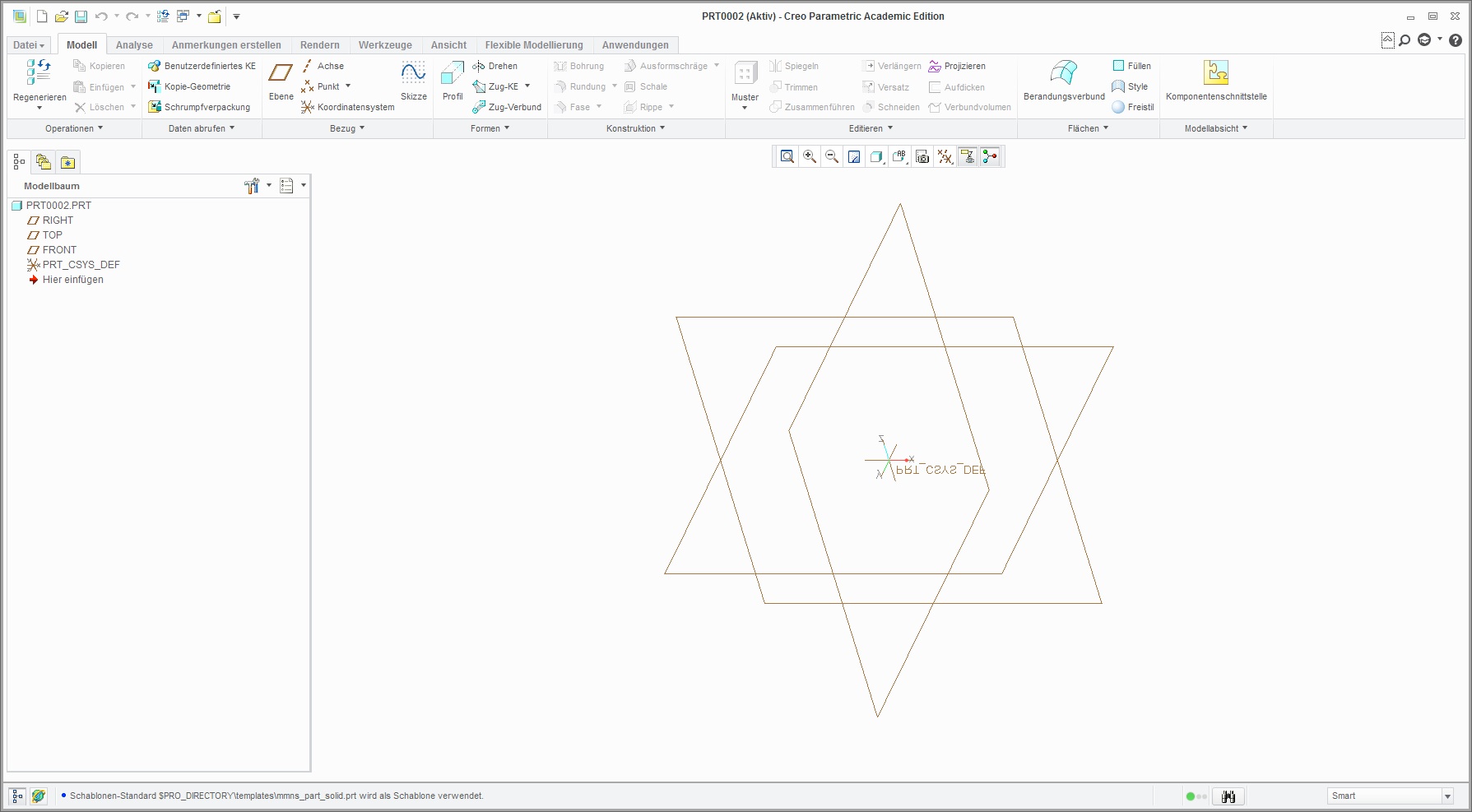
It seems that every model i am viewing and the whole vieport is inverted.
That means that all labels of coordinate systems and axes are inverted.
I will make a screen shoot so maybe you can see what I mean:
As you can see the toolbar and everything else is normal, but the view port is inverted and also the position of the mouse, wich makes it hard to work with it...
- Mark as New
- Bookmark
- Subscribe
- Mute
- Subscribe to RSS Feed
- Permalink
- Notify Moderator
There is not concept of a view port orientation in Creo, the coordinate system is based on the model you are viewing. If you create a new part or assembly using a template model, those template models will have a coordinate system in them.
If you configure Creo using one of the Academic Program configurations found in the "creo_standards" folder, the direction of the Z Coordinate will be pointing up as is typical in most CAD systems.
If you are using Creo out of the box (unconfigured), you are using the commercial template models and the Z Coordinate direction of those models does not point up.
- Mark as New
- Bookmark
- Subscribe
- Mute
- Subscribe to RSS Feed
- Permalink
- Notify Moderator
I have used one of the standard configurations and it´s still the same...
Here is a screenshot when I try to make a new part
- Mark as New
- Bookmark
- Subscribe
- Mute
- Subscribe to RSS Feed
- Permalink
- Notify Moderator
The coordinate system in your image is that of a commercial template part so you have not configured your installation using one of the Academic Program configuration options.
In the image below the coordinate system named PRT_CSYS_DEF is that of a commercial template model. You will get this if you do not use one of the Academic Program configurations. The coordinate system named DEFAULT_CSYS is from one of the Academic Program templates.
It also be noted again that there is no view port orientation concept in Creo. If you want to change the orientation of a coordinate system, you can edit its definition and change it. You could also have multiple coordinate systems in a model, each pointing in a different orientation.

- Mark as New
- Bookmark
- Subscribe
- Mute
- Subscribe to RSS Feed
- Permalink
- Notify Moderator
Adam, I don't understand what you are saying... it is the CSYS tag that is "mirrored" in Andreas' images. The text should be right reading to the screen at all times. It is not the orientation of the CSYS he is worried about.
- Mark as New
- Bookmark
- Subscribe
- Mute
- Subscribe to RSS Feed
- Permalink
- Notify Moderator
I guess that I miss-understood the problem then. Is this simply a graphics issue? If so, please see this post for more information on graphics options.
Sorry for the confusion.
Adam
- Mark as New
- Bookmark
- Subscribe
- Mute
- Subscribe to RSS Feed
- Permalink
- Notify Moderator
Adam,
So why this difference between student and comercial default CSYS orientations does PTC want student users to be drawn to UGNX so the csys is familiar?
NX and Catia both use Z as the default Up direction for Top Plane
SolidWorks, Proe & Alibre use Z as the default Direction for Front facing datum being XY
Interesting but most likely confusing if what you say regarding the Educational CSYS is true.
Just Saying.
Michael
P.S. to fix issue you'll need to open up the Start Part Default and reset your Front View to apply to viewing the XY plane and overide the rest of the views and resave them. Having multiple csys will definately help when exporting to neutral file types to be opened in other programs.
- Mark as New
- Bookmark
- Subscribe
- Mute
- Subscribe to RSS Feed
- Permalink
- Notify Moderator
Hi Michael,
The orientation of the CSYS (among other things) is based on industry standards for those specific configurations. This does not have to do with a difference between student and commercial editions.
Typically, people think of the X and Y axes facing to the right and up, respectively, and the Z axis is into/out of the page. This would equate to the orientation of the CSYS in the default configuration.
However, certain industry standards orientate the CSYS in a different manner. Specifically, those standards orientate the Z axis facing up, the Y axis into/out of the page and the X axis stays the same. These standards are seen in real-world applications, not just in CAD software.
We have provided configurations based on these standards as well as a default configuration so that the user can use a variety of configurations based on their specific application or what makes sense to them. For example, if a Formula SAE team needs to work specifically according to ASME standards, they would most likely configure Creo using one of the ASME configurations we have provided. If you are not working in a specific application, then I would suggest using whichever orientation makes the most sense to you.
Hope this helps!
Regards,
Curtis Siebenaller
- Mark as New
- Bookmark
- Subscribe
- Mute
- Subscribe to RSS Feed
- Permalink
- Notify Moderator
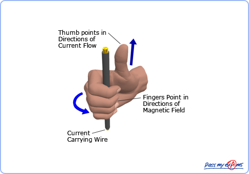
A quick Google about this shows that the notion has completely lost its true meaning. Originally it was the "right hand rule" ...
 ...and this related to the "top" view (as in looking down onto the drafting board). If you do this search today, you will see some wild ideas.
The "default" for PTC is Z facing "forward"... I call this the "easel" view. This is what you get when you open an empty part. Since drawings are always oriented with "Z up", it really doesn't matter which way they orient.
In practice, I never gave it much thought, but it does explain why some parts do not assembly as expected when I mix templates. Thinking about it, I would rather have Z "pointing into the air", so to speak so the X-Y plane should be oriented when looking down on the part and gazing slightly to the right to face the "front" plane.
Other "consistent" hand references:


...which became the norm for positive rotation about an axis (thumb = +Z; fingers = positive rotation).
- Mark as New
- Bookmark
- Subscribe
- Mute
- Subscribe to RSS Feed
- Permalink
- Notify Moderator
The arguments put forward all have weight and show thing shave become confused over time with no accepted global standard.
I first heard this explanation by a CAD tutor in the early 1980s. "Early 2D CAD systems used the standard used in mathematics of x axis horizontal and y axis vertical. When CAD moved into 3D wire frame, the z axis became 'out of the page'. A default 3D view was needed so they tilted model space a little leaving the z axis still pointing out of the screen".
I have no idea how the Z axis came to be vertical in current CAD systems.
When the education templates for Pro|ENGINEER were first created, pictorial views including isometric and trimetic were top of the list to make it easy to orient models for rendering and in drawings. I am puzzled why professional engineers don't ask for these views in the default config?
Choosing the education coordinate system direction was influenced by the axes in 3 axis mills and routers. Most of the machines in schools, colleges and universities use Z for vertical movement. If a student creates a model to be machined, the default pictorial views display the model as it will be seen on the bed of the NC machine.
- Mark as New
- Bookmark
- Subscribe
- Mute
- Subscribe to RSS Feed
- Permalink
- Notify Moderator
I have the same problem. Is there any solution, yet ? ![]()
- Mark as New
- Bookmark
- Subscribe
- Mute
- Subscribe to RSS Feed
- Permalink
- Notify Moderator
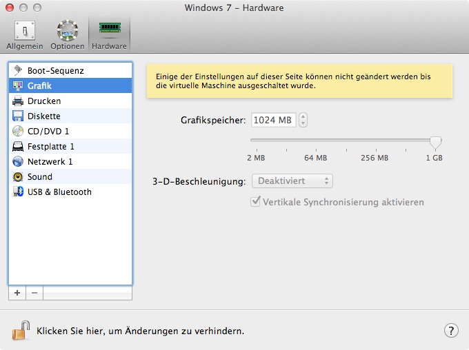
yes! it worked for me
I deactivated Direct X
- Mark as New
- Bookmark
- Subscribe
- Mute
- Subscribe to RSS Feed
- Permalink
- Notify Moderator
Heey thank you so so much, it works ! ![]()
- Mark as New
- Bookmark
- Subscribe
- Mute
- Subscribe to RSS Feed
- Permalink
- Notify Moderator
Hi,
I am a first year engineering student at york university and its my first year working with creo. Although I am not sure how to deal with the axis problem, I can answer the question where a real world application uses a z axis that is up and down and the y axis is in and out.
The machine shop at my unversity has 2 mills which have their axis labelled as x-> sideways, y-> in and out and z-> up and down. I was completely confused when I used the machine for the first time. When I asked the machine shop guy, he said in all 30 years of his experience he has always worked with milling machines labelled like ours! So i guess in real world applications the z axis is up and down while the y axis is in and out.
Anirudh
- Mark as New
- Bookmark
- Subscribe
- Mute
- Subscribe to RSS Feed
- Permalink
- Notify Moderator
FYI,
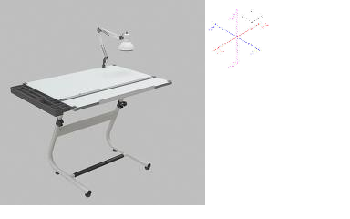
Most CAD systems are or were based on the drawing board, which lays the current view from the monitor flat on the drafting table.
When you look down at the paper Z is in and out of the paper. X is left to right edges of the paper. Y is back edge of the paper to the front edge of the paper. Take the drawing to the shop and lay it on the machine table and it matches.

So the problem is not the orientation of the X,Y,Z in the design tool.
Changing the default component/assemble coordinate of the design model to match the machine that may be used to manufacture the design assumes you know how the design will be manufacture when you start the design process.
It is extremely easy to add the relevant coordinate system after the design work is done. While manufacturing should always be considered during the design process, at this point in the workflow focusing on design is far more important. Many designs may be done before even deciding which one will be made or prototyped (the prototype will more then likely be made on a different machine then the finished product).


