
Turn on suggestions
Auto-suggest helps you quickly narrow down your search results by suggesting possible matches as you type.
Showing results for
Please log in to access translation
Turn on suggestions
Auto-suggest helps you quickly narrow down your search results by suggesting possible matches as you type.
Showing results for
Community Tip - Have a PTC product question you need answered fast? Chances are someone has asked it before. Learn about the community search. X
- Community
- Creo+ and Creo Parametric
- 3D Part & Assembly Design
- Drawings unstable in Creo 2.0?
Translate the entire conversation x
Please log in to access translation
Options
- Subscribe to RSS Feed
- Mark Topic as New
- Mark Topic as Read
- Float this Topic for Current User
- Bookmark
- Subscribe
- Mute
- Printer Friendly Page
Drawings unstable in Creo 2.0?
Jun 22, 2012
02:28 AM
- Mark as New
- Bookmark
- Subscribe
- Mute
- Subscribe to RSS Feed
- Permalink
- Notify Moderator
Please log in to access translation
Jun 22, 2012
02:28 AM
Drawings unstable in Creo 2.0?
I just completed a very comprehensive machining drawing and I must say that between 2000i and Creo 2.0, the drawing had become seriously unstable.
1st I was dealing with some very annoying graphics artifacts. Ones where simply moving an annotation feature would blank out the feature. More often than not, I would have to regenerate the drawing to get things to unhighlight or come back to a visible state. Seriously annoying indeed!
Then I had whole blocks of dimensions and other features just -move-. They jumbled themselves up left and right generally undoing a lot of careful placement that I was -doing-. It happened sometime between switching to the model and drawing, and poof, I again had to fix a couple of dozen annotation features.
Am I the only one? ...or is this something that has become the norm? Seriously, in 2000i, it was set it and forget it. Now I don't know how people keep from pulling their hair out.
I am on an approved platform with the approved drivers... etc.
This thread is inactive and closed by the PTC Community Management Team. If you would like to provide a reply and re-open this thread, please notify the moderator and reference the thread. You may also use "Start a topic" button to ask a new question. Please be sure to include what version of the PTC product you are using so another community member knowledgeable about your version may be able to assist.
Labels:
- Labels:
-
General
141 REPLIES 141
Jun 26, 2012
04:30 PM
- Mark as New
- Bookmark
- Subscribe
- Mute
- Subscribe to RSS Feed
- Permalink
- Notify Moderator
Please log in to access translation
Jun 26, 2012
04:30 PM
I'm not on Creo 2.0 yet... but I never jump on brand new software from any company until it's had the kiks worked out a little first. Creo 2.0 was just officially released at M010. Before that it was in what I call "take your chances" mode, release level F000 and F001.
I'm not saying this is definitely a bug or a problem with Creo 2.0, I'm just saying I prefer not to leap to such white hot new software offerings so soon after their release to avoid such issues. For an issue such as this, you may need to call PTC customer support. Perhaps they're aware of a problem that can be easily resolved.
Best of luck...
-Brian
Jun 26, 2012
04:43 PM
- Mark as New
- Bookmark
- Subscribe
- Mute
- Subscribe to RSS Feed
- Permalink
- Notify Moderator
Please log in to access translation
Jun 26, 2012
04:43 PM
I kind of looked at Creo 1.0 as the test bed for 2.0. There is already an update for 2.0 to M010?
At the moment, I can afford the learning curve and instability. But that won't last too long.
Jun 26, 2012
05:38 PM
- Mark as New
- Bookmark
- Subscribe
- Mute
- Subscribe to RSS Feed
- Permalink
- Notify Moderator
Please log in to access translation
Jun 26, 2012
05:38 PM
I'd love to hop on Creo 2 but for the kind of organization I work for, we need stability. My choices are to keep us on Wildfire 5 until Creo 2 is out for many months... or hop to Creo 1.0 now. My reasoning for going to Creo 1 now is that at the very least we'll have all our people trained on the new interface now. This should make the eventual jump to Creo 2 or 3 much easier.
Jun 29, 2012
02:49 PM
- Mark as New
- Bookmark
- Subscribe
- Mute
- Subscribe to RSS Feed
- Permalink
- Notify Moderator
Please log in to access translation
Jun 29, 2012
02:49 PM
Funny you should say that about the interface.
I feel we now have 3 interfaces... Classic, WF, and Creo.
I used classic for years and was quite happy with it. It was easy to focus on command and prompts.
Then I used WF4 for a few months. I wasn't impressed but I found what I needed to find relatively easily.
Now with Creo under my belt for several months (1.0 then 2.0), I feel the Creo ribbon interface is quite a bit more cumbersome as I seem to be clicking a lot more, rather than the touted "less clicks" Plus, I am looking all over the screen to find prompts. The "classic" prompts are off on the upper right corner; the "command line" prompt doesn't show up without moving the bottom of the window; The WF prompts are the same as WF (which still bug me).
Before jumping on Creo 1.0, I would definitely have a session with all the users to go through the PTC University introduction to the new ribbon interface and be ready to use it soon after.
I don't like the ribbon in MS OFFICE and I don't like it in Creo. It is -very- limited, and targeted to a way of working PTC envisions, not for what I do on a day to day basis. This is definitely a scenario of one size does -not- fit all. And I certainly do not have the bandwidth to be re-arranging menus only to risk loosing the effort between updates/upgrades.
I might have to try installing 2001. Am I correct in assuming that my current license file will authorize any version I want to use? Is anyone else running a slew of Pro/E versions on a single license install?
Jun 29, 2012
04:04 PM
- Mark as New
- Bookmark
- Subscribe
- Mute
- Subscribe to RSS Feed
- Permalink
- Notify Moderator
Please log in to access translation
Jun 29, 2012
04:04 PM
Ah Antonius...
You missed a massive thread about 2 months back where everyone vented their frustrations over the interface changes. This is well-covered territory. I use the ribbon... but I also find myself using many mapkeys and a customized quick access toolbar to short-circuit. I'm doing my best to work with it as I experiment with ways to use it more efficiently.
To answer another question, I do know you can certainly run multiple versions of Pro/ENGINEER (at least the Wildfire versions) with a single license file. Now maybe that license file contains options for each version- I'm not sure about that point. But for quite awhile we were running Wildfire 2, 3, and 4 all at the same time. Now we've standardized on Wildfire 5 and we're preparing to go live with Creo Parametric 1.0 within the next couple of months. I'm not sure if you can go all the way back to 2001 without a special license.
My understanding is that you certainly should be able to run that software... and if your current license cannot handle it, I would suspect someone at PTC Customer Support could provide one that did. It may not be easy because of how old the software is... but I'm sure they must have other customers issuing such requests now and then.
While I love (and I mean looooooove) 2001, I would not want to go back. I've become too accustomed to some of the newer tools to go back. But what I have always advocated was giving the users a chance to customize and create the interface they want. At the Planet PTC Live event in Orlando, I asked some of the Product Line managers for PTC if they would ever consider giving us the ability to create "Skins" for Creo. For awhile, giving users the power to create a new "skin" for a tool was very, very popular. If anyone remembers WinAmp, there were hundreds of skins for that application that proved very popular.
If we had the ability to create our own interface, we could make the tool look however we wanted. If we wanted text menus, we could have them. If we wanted a dashboard, we could have it, too. If we wanted a ribbon down the right hand side- that should also be an option. Other CAD systems (back in the 2D era) gave us this type of flexibility.
Granted, Creo is a supremely more complex product. I can imagine the headache involved in giving us a flexible interface... but I still believe there's a case to be made for such an effort. One needs only to look at the way products such as AutoDesk MAYA can be customized to recognize the benefits of giving users that power. Imagine giving Creo customers (companies/users/etc) the ability to modify the interface to streamline it for real world needs. But not to get off on a tangent!
Have a great weekend!!
-Brian
Jun 30, 2012
01:24 PM
- Mark as New
- Bookmark
- Subscribe
- Mute
- Subscribe to RSS Feed
- Permalink
- Notify Moderator
Please log in to access translation
Jun 30, 2012
01:24 PM
In response to user comments, it may well be that PTC is already looking seriously into "roles" like Unigraphics did in NX. This is somehting a 3rd part could do with the interface today.
I am not clear yet as to how customizable the interface really is. I just keep dumping commands on the little toolbar over the tree window. Many don't even have icons assigned to them, which is really sad.
I remember WinAmp. Loved it!
Jul 16, 2012
01:16 PM
- Mark as New
- Bookmark
- Subscribe
- Mute
- Subscribe to RSS Feed
- Permalink
- Notify Moderator
Please log in to access translation
Jul 16, 2012
01:16 PM
In Creo 2.0 just right-click on the ribbon and you can customize its presentation. You can move commands around, hide/create groups and even hide/create tabs.
It's also possible to change the presentation style for each command so big ones can become small and vice-versa; you can also toggle the visibility of the command's label.
Jul 16, 2012
02:45 PM
- Mark as New
- Bookmark
- Subscribe
- Mute
- Subscribe to RSS Feed
- Permalink
- Notify Moderator
Please log in to access translation
Jul 16, 2012
02:45 PM
I need to go through that tutorial again. I have not had much luck with this as yet.
My fear also comes in that a lot of times, you loose all that customizing work with new revisions. Over the decades, time spent personalizing menus was often wasted or simply lost when you have no clue as to what files to preserve or how to recall them. It just seemed like an exercise in futility.
Having said that, I noticed that from F001 to M010 Creo 2.0, my quick menu seemed to have remained in tact. I still don't know why but it made me happy. I even uninstalled F001 completely, and the menu files remained. <scratches head>. I don't know just how transportable my experience is. one things I would definitely add to the customizing ribbon interface dialog is whether to add the command to all the common ribbon tabs (drawing, assembly and part) or just the current version. I did have to add the same button 3 times to get "common" menus (3x + 1 for the "no part open" window).
The idea behind roles is that, by default, certain functions can quickly be recalled. Maybe I am simply modeling machine parts one day and the next, I am heavy into annotation. I can call up a predefined "role" for each session. The following project is heavy into plastic design. This is a completely different role, of course, so I want surfaces and mold tool icons at the ready.
Another upgrade would be using the command finder to build ribbons and tabs with drag and drop from the finder. Drag and drop in general should be much more user friendly with any interface today. I'm sure I am missing somehting here, but at the moment, I can't make the menu system work for me. Again, I will go back through the tutorial and comment further. But I do, and would appreciate further comment in this regard here in this sub-thread.
I think this request is more an idea of "fit and finish" to the interface.
Jul 09, 2012
02:07 PM
- Mark as New
- Bookmark
- Subscribe
- Mute
- Subscribe to RSS Feed
- Permalink
- Notify Moderator
Please log in to access translation
Jul 09, 2012
02:07 PM
What my friend Brian is talking about is a few of MY threads where I, and a ton of others, vented about the dreaded "file of feotid dingos kidneys" creo interface.  You should check them out.
I completely agree. I don't like the WF interface, but I can get by with it. The creo interface, flat s#cks the aformentioned kidneys......
Best of luck.........
Jul 09, 2012
02:25 PM
- Mark as New
- Bookmark
- Subscribe
- Mute
- Subscribe to RSS Feed
- Permalink
- Notify Moderator
Please log in to access translation
Jul 09, 2012
02:25 PM
lol... don't mince words Tell us what you really think.
Jul 06, 2012
11:59 AM
- Mark as New
- Bookmark
- Subscribe
- Mute
- Subscribe to RSS Feed
- Permalink
- Notify Moderator
Please log in to access translation
Jul 06, 2012
11:59 AM
The artifacts that you are seeing could be a display driver issue with Creo 2.0. See if there is a newer driver for your video card.
Jul 06, 2012
12:14 PM
- Mark as New
- Bookmark
- Subscribe
- Mute
- Subscribe to RSS Feed
- Permalink
- Notify Moderator
Please log in to access translation
Jul 06, 2012
12:14 PM
I updated to M010 since this post and also updated my Nvidia drivers.
I now have new issues with datums not moving on drawings and planes not following visibility settings when datum tags are attached.
I seem to remember that GD&T in Pro/E has always been a bit flacky and it seems to continue today.
Jul 06, 2012
12:53 PM
- Mark as New
- Bookmark
- Subscribe
- Mute
- Subscribe to RSS Feed
- Permalink
- Notify Moderator
Please log in to access translation
Jul 06, 2012
12:53 PM
Hi Antonius...
Because the weird problems are actually CHANGING as your driver changes, it really seems like a driver issue. Have you tried switching to software graphics to see if that removes the issue? Does your NVidia driver have an optimization setting for Creo (or Pro/E)? Or... maybe a better way to help would be to ask what graphics card you have... that will give us some clue to help us suggest possible fixes.
Thanks!
-Brian
Jul 06, 2012
01:23 PM
- Mark as New
- Bookmark
- Subscribe
- Mute
- Subscribe to RSS Feed
- Permalink
- Notify Moderator
Please log in to access translation
Jul 06, 2012
01:23 PM
I think the F001 to M010 was a bigger change than the graphics driver. The again, it does change during the session as well.
The latest Nvidia driver supports Creo 2.0 and it is selected for the application. My GPU is the M3000 in the Dell Precision M6600. It is a supported card and a supported platform.
I just put in a support case as the datum tags are really driving me up a wall. The datum planes associated with datum tags won't hide regardless of hidden states. I've always had trouble working GD&T properly in 2000i and now it still has issues in Creo 2.0. It is time to get to the bottom of this.
The other problem I've been having in M010 is moving views... selecting items in general, actually. The sessions gets into a state where clicking a view come up with the "use Alt key..." where moments before the views were selecting fine. I noticed that other selections were failing after this as well. Once this happens, there is no recovery. It was after this that things really got weird with moving datum tags. This is definitely a bug in Creo where a reboot of Creo fixes it. The issue is not saved with the part, thankfully.
Jul 06, 2012
04:54 PM
- Mark as New
- Bookmark
- Subscribe
- Mute
- Subscribe to RSS Feed
- Permalink
- Notify Moderator
Please log in to access translation
Jul 06, 2012
04:54 PM
hi,
I am running Creo Parametric 1.0 since the beginning of this year and now also Creo Parametric 2.0 M010 since today. Been using F000 and then F001 of Creo Parametric 2.0 since they came out.
Using Nvidia Quadro 400 in my Workstation and so far I have had no problem with same or similar graphic issues in Creo Parametric.
I recommend trying older driver. I can check what version of Nvidia driver I have at work and let you know, it should be compatible with your graphics card as well.
It always goes this way with new computers and hardware, once you find the drivers that work for you then you are set. The latest is not always the best.
You have to know that WinAmp still exists and its the best mp3 player I know Been using it forever and still using it these days with its very classic scheme.
Antonius, I curious what do you mean by "the "command line" prompt doesn't show up without moving the bottom of the window"
I have had trouble with popups while hovering with mouse over objects and commands before I was going to select them. They were showing all over the place and quite slowly. The config.pro option enable_popup_help set to no solves this annoying issue quite well while putting these popups right on top of the command line and they show INSTANTLY.
~Jakub
Jul 06, 2012
05:47 PM
- Mark as New
- Bookmark
- Subscribe
- Mute
- Subscribe to RSS Feed
- Permalink
- Notify Moderator
Please log in to access translation
Jul 06, 2012
05:47 PM
Thanks for the tips. I guess I have to qualify a couple of statements.
It is very hard to trace hardware, platform, and application problems. I fully appreciate the delicacy of Pro/E in relation to the platform and even the drivers. Being that the platform is "qualified" by PTC, and not knowing the optimum driver at this point, I can only say that drawings have become more stable after the upgrades, which were unfortunately done at the same time.
Today I spent over an hour with tech support on a corrupt drawing. This had to do with datums not moving until after a regen. Right now, all my issues are with GT&D features. We were able to reproduce the issue of datum planes not hiding after assigning a datum tag on both the support tech's computer and on my computer with a brand new part. However, on the new part, moving this same datum tag on the drawing worked fine while in the corrupt drawing, the datum would not move without the regen. We copied the files and simplified it to protect my client's interest and the problem remained in the submitted file. I had CXreo 2.0 M010 crash twice; the second time I submitted the crash log to support as well.
I also tried changing models in the drawing and for some reason, nothing happened. Relations that showed in the format too did not update. I ended up deleting all views and the format and bringing the drawing back to a very basic 3 view borderless drawing and the issue regarding moving the datum tag (tagged to a datum plane) remained.
Again, usability of GD&T through annotation has always been a weak link in Pro/E. It might have even gotten worse in my recent experience. I was being bold to give it a new chance. I see I am hurting myself more than helping myself by doing so. I've lost a good half day chasing this issue already. My client's schedule doesn't allow for such downtime.
the only blessing in all this is that the drawing does not require sustainability. If it had, I would have had to start over completely to ensure a non-corrupt file.
Proper use of annotation and GD&T is something that is still quite criptic. The inability of being able hiding datum planes when tagged is a mystery; as is the fact that if it is one of the default datum planes, it hides and won't come back no matter what. The only good thing is that soon this should be logged in the issues list. The types of drawings I do can take 2-3 days to create. Not something where I can afford to let file corruption to force me to redo work.
So Jakub... do you use the model annotation for GD&T implementation on your drawings?
Jul 06, 2012
06:06 PM
- Mark as New
- Bookmark
- Subscribe
- Mute
- Subscribe to RSS Feed
- Permalink
- Notify Moderator
Please log in to access translation
Jul 06, 2012
06:06 PM
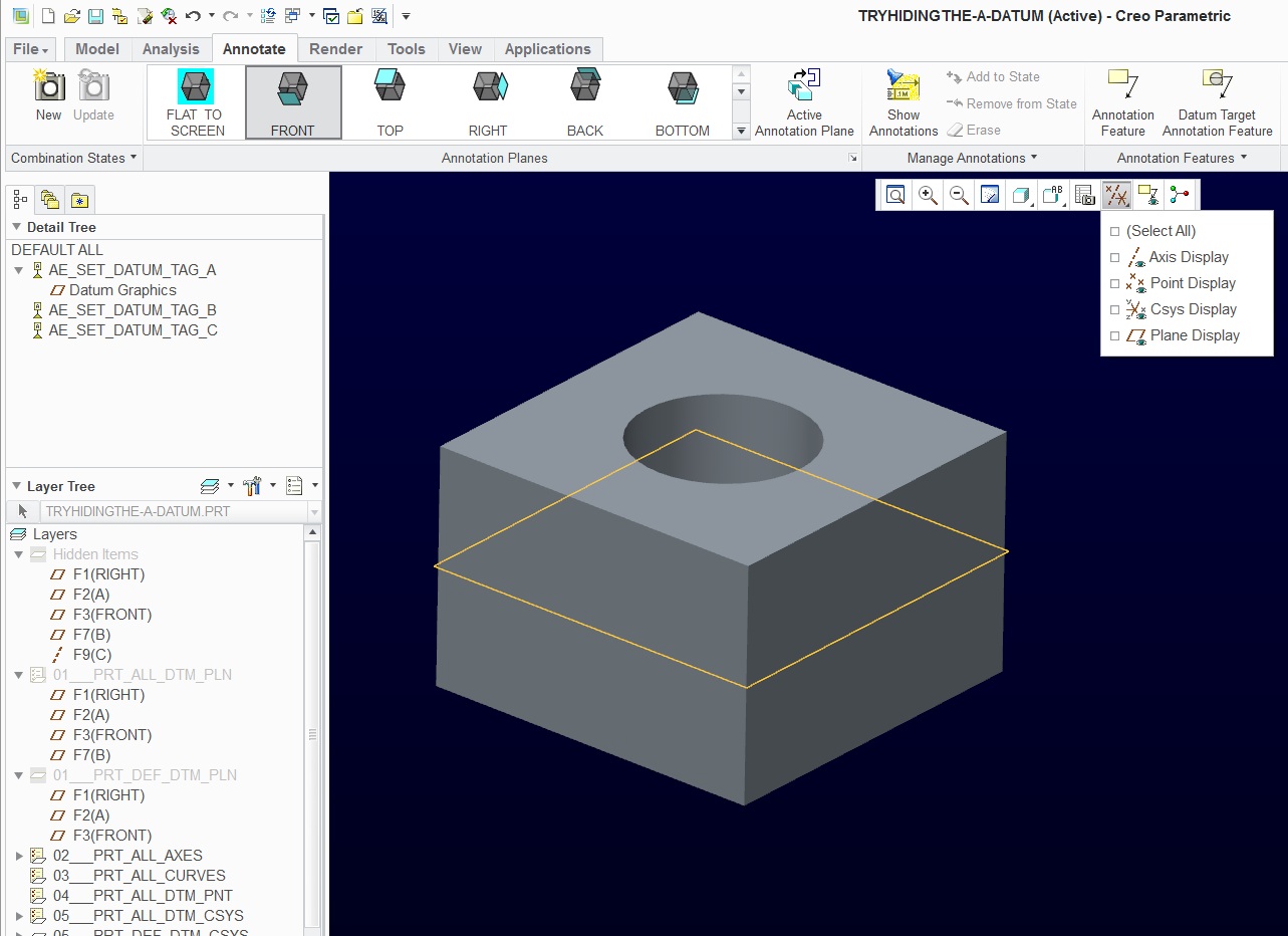
Here is a sample: The file is attached.
3 datum tag types are included: A plane (A); a planar surface (B), and a cylinder surface (C) (which attaches to an axis).
There is no way that I can find to hide the [A] datum plane.
I have also had this datum permanently hide when attached to the RIGHT datum. In that case, the datum won't show unless selected in the tree.
 .
.
Jul 07, 2012
03:55 AM
- Mark as New
- Bookmark
- Subscribe
- Mute
- Subscribe to RSS Feed
- Permalink
- Notify Moderator
Please log in to access translation
Jul 07, 2012
03:55 AM
Ok, I see you have managed to turn the annotations off either by hiding or by switching the annotation display.
You also have the datum plane "A" in hidden items layer. As I can't really see the model tree I am not sure whats going on there. Will have a look at your model on monday when at work.
I notice that you have all datum features turned off and that one datum plane still shows up. It doesn't have the "A" tag next to it which is odd but maybe you have datum plane tags turned off by config.pro option.
The only remaining way how you could turn the display of that datum plane off is under File --> Options --> Model Display --> and then unticking the option called "Show datum features" or something like that.
If that doesn't work then there's something wrong with your model. I hightly doubt this has to do something with your graphics card or its drivers.
Good luck.
~Jakub
Jul 09, 2012
02:32 PM
- Mark as New
- Bookmark
- Subscribe
- Mute
- Subscribe to RSS Feed
- Permalink
- Notify Moderator
Please log in to access translation
Jul 09, 2012
02:32 PM
Looks like something is wrong with the image server. Here it is again.
Jul 09, 2012
11:26 PM
- Mark as New
- Bookmark
- Subscribe
- Mute
- Subscribe to RSS Feed
- Permalink
- Notify Moderator
Please log in to access translation
Jul 09, 2012
11:26 PM
I moved the default coordinate system above plane A and referenced it, as the plane was not referenced. I suppressed the anotation feature. In the properties box, I changed the datum to the first type. The plane would then hide. I then changed the datum to the second type and all was well. When I unsupressed the annotation for A, it failed. I deleted it and created another annotation for it and it would not hide anymore!. I don't know if this helps at all in the investigation of this issue. I don't use the datum types or the annotations in any of my work.
Jul 10, 2012
01:17 AM
- Mark as New
- Bookmark
- Subscribe
- Mute
- Subscribe to RSS Feed
- Permalink
- Notify Moderator
Please log in to access translation
Jul 10, 2012
01:17 AM
Thank you. You are seeing exactly what I am seeing.
I have a feeling I will be escalating this issue in support.
Today I was told that this was desired behavior... that annotation would not hide with layers. D'UH! I'm not talking about annotation... I am talking about the plane. I am quickly loosing faith in my efforts to make very detailed support posts. Every time I find myself asking if the support person even tried this for themselves. Don't even ask me to elaborate.
Anyone know how to see an SPR by the value?
Here is what I got back today... and remember, the tech -saw- this on my screen and his:
- This issue has already been reported to R&D as SPR 2124460
- SPR was resolved as ‘Works to product specification’ for Creo Parametric 1.0 and later
- Starting from Creo Parametric 1.0, display of Annotations cannot control by layers
- Create combined views/states to control the display of annotations.
- Starting from Creo Parametric 1.0, new interface has been introduced for using annotations (creating and presenting them) in 3D models. Combined states are now more similar to views of the model. The workflow is to create the view (combined state), then create/show the annotations the user wants to have visible when that state is active. Annotations created while a combined state is active are automatically set to be displayed in that combined state
Excuse me, but how do you create a "desired" view state if you can't get a view that you desire with -NO!- datum planes showing.
Jul 11, 2012
12:05 PM
- Mark as New
- Bookmark
- Subscribe
- Mute
- Subscribe to RSS Feed
- Permalink
- Notify Moderator
Please log in to access translation
Jul 11, 2012
12:05 PM
How is this talk about combined state supposed to be in the report?
Why are they talking about layers? The issue lies completely elsewhere. You should be able to hide these datums without the use of layers. 
Jul 11, 2012
12:28 PM
- Mark as New
- Bookmark
- Subscribe
- Mute
- Subscribe to RSS Feed
- Permalink
- Notify Moderator
Please log in to access translation
Jul 11, 2012
12:28 PM
I pressed the issue and a new SPR was submitted.
I noticed that once these datum tags were used on a drawing, the datum would permanently disappear from the model graphics, making them unusable for further construction without picking them in the model tree.
The Combined States is not a layer, but something else, something I always associated with assembly file tools for drawings. It does work, but it is a work-around, certainly not a solution. I think it was deemed a solution since it also works with annotation. Then again, a datum plane is -not- an annotation feature... it is a datum feature. And its control lies squarely in construction.
This is part of an old bug that has been excussed away for nearly a decade. Back in pre-wildfire days, annotation would destroy usability of GD&T in models due to the cluttered mess it left in large assembly models. This is simply a remnent of that code.
Jul 11, 2012
12:40 PM
- Mark as New
- Bookmark
- Subscribe
- Mute
- Subscribe to RSS Feed
- Permalink
- Notify Moderator
Please log in to access translation
Jul 11, 2012
12:40 PM
Great that they are willing to reinvestigate the issue.
I only use combined states when I want to see some of my models in assembly in transparent view state, so thats why I asked the question.
Anyway I thought annotations on model level are also datums. Like lets say you can switch them on and off with annotation display button whenever you want.
So even if that datum plane became an annotation plane... it doesnt make sense.
You should be able to turn the mess off at least on the latest version of Creo.
Jul 11, 2012
02:54 PM
- Mark as New
- Bookmark
- Subscribe
- Mute
- Subscribe to RSS Feed
- Permalink
- Notify Moderator
Please log in to access translation
Jul 11, 2012
02:54 PM
Oh, yes... today we can easily hide annotation with a single button. Hence my insistence in fixing this datum plane visibility issue.
Maybe I should clarify the difference between Datum as construction tools and Datum Tag as annotation. Just because a feature is annotated, or tagged, doesn't, and shouldn't change the "nature" of the original feature.
The problem is that there are so many kludges in the software to make it "appear" as some big customer demanded, that they have coded themselves into a corner. When you pick a surface, cylindrical or planar, the system attaches a tag to a datum plane or axis which the software generates just to make the annotation feature. I'm sure there is good reason for this, and indeed, these axis and planes should remain hidden in every sense of the word as long as they are solely for the purpose of maintaining the tag. We should not be encumbered by these as all I cared about was the surface and the annotation. The surface doesn't disappear or have any other restrictions, no? So neither should a user generated datum plane be treated any differently when tagged with a datum annotation.
The company I worked for a decade ago went form Pro/E to UG NX. After the emotional trauma was over, no one ever looked back except me and one other engineer. Now I am scratching my head as to why. Seems nothing really changed in 10 years inn the core product. (answer to why: running Windows NT 4.0 on a P4-486 for 2000i was cumbersome). This is a sad testimony. I might just look a lot harder at SolidWorks.
But the support team did send me a fine Corinthian leather folder
Jul 11, 2012
04:25 PM
- Mark as New
- Bookmark
- Subscribe
- Mute
- Subscribe to RSS Feed
- Permalink
- Notify Moderator
Please log in to access translation
Jul 11, 2012
04:25 PM
Cool, lets see whats in that folder 
I was gonna ask if right now its not better to just set up few symbols and try to draw the geometric tolerances and tags in the sheet directly. Without having to define annotations in the model and so on.... all in Creo ofc.
But that means going back to level 0.
Jul 11, 2012
05:04 PM
- Mark as New
- Bookmark
- Subscribe
- Mute
- Subscribe to RSS Feed
- Permalink
- Notify Moderator
Please log in to access translation
Jul 11, 2012
05:04 PM
The Tech Support folder contains solution to all my problems!  A link to PTC.Support.Com
I have been spending my "spare" hours on this issue. A few thing have cropped up already:
1. I cannot make an ISO [A] tag (note with triangle arrow) on a horizontal face without having the leader tail. Not per standards.
2. You cannot make GD&T feature control frames using draft datums, GD&T datums -have- to be defined in the model to use the GD&T feature frames in both drawings and models.
3. Weird things happen to feature control frames. They tend to "collapse" as in "word wrap" and there is no way to recover them. This one will probably get reported by me as a serious bug. Just don't touch that little white cube at the end of GD&T text string when moving stuff on the drawing. And no, tech support... that is -not- a solution!
Being at level zero is the norm since this has never worked for me in the past. I liked it a lot better with the [-A-] datum symbols on the drawings. The only thing that is challenging me now is the new style datum symbols and the bugs... like drawing corruption; exploding feature control frames; cumbersome interface... etc.
Jul 16, 2012
04:16 AM
- Mark as New
- Bookmark
- Subscribe
- Mute
- Subscribe to RSS Feed
- Permalink
- Notify Moderator
Please log in to access translation
Jul 16, 2012
04:16 AM
We are investigating the drawingless process right now as part of some of the OEM requirements.
Just a few words on the combined states:
- they let you organize what would be the views in 2D.
- In a combined view (for 3D annotation purposes) you can manage:
- 3D view orientation
- X-Section (and its visibility)
- annotation visibility
- 3D view zoom factor (for smth. like a detail view)
So when set up properly you can browse through your combined states (in creo 2 with the help of tabs at the bottom of the screen) which will reorient/ zoom/ section your view and hide/ show annotation to display only what should be visible in this view.
So you end up with a set of combined view that can be reused when creating a drawing.
If a drawing template is used you can just reuse your combined views with everything taht is defined there.
Also the anotations inkl. the combined states can be reused in the CreoView visuatisations (also in WINDCHILL of course).
So anyone in the process with no creo installation can also browse through the view startes easily.
The overall usability is still somewhat jerky and managing the annotations for each view going from WF4 (layer visibility in combined view) to creo 2 (activation of combined view when creating the annotations with the ability to move them later between the states) is still a step back in my opinion.
Also picking referneces and the logic behind where the annotation are placed (internal parallel planes to the actice view plane) is unsatifactory.
Since we do not have a choice we will have to productively use 3D annotated models in the near future. They also bring some nice things with them: reuse of the 3D tolerances on our computer tomograph measuring machines. Using a 3rd party software we can import them from creo and map them onto the scan model. This was a long a tedious process before.
Jul 16, 2012
12:13 PM
- Mark as New
- Bookmark
- Subscribe
- Mute
- Subscribe to RSS Feed
- Permalink
- Notify Moderator
Please log in to access translation
Jul 16, 2012
12:13 PM
I like seeing success stories in the 3D annotation front. I can certainly see the advantages for certain functions.
I can draw a relatively complex drawing in about a day.
Do you think someone could do a complete 3D annotation in a day?


