
Turn on suggestions
Auto-suggest helps you quickly narrow down your search results by suggesting possible matches as you type.
Showing results for
Please log in to access translation
Turn on suggestions
Auto-suggest helps you quickly narrow down your search results by suggesting possible matches as you type.
Showing results for
Community Tip - Your Friends List is a way to easily have access to the community members that you interact with the most! X
- Community
- Creo+ and Creo Parametric
- 3D Part & Assembly Design
- RE: Advanced ISDX questions
Translate the entire conversation x
Please log in to access translation
Options
- Subscribe to RSS Feed
- Mark Topic as New
- Mark Topic as Read
- Float this Topic for Current User
- Bookmark
- Subscribe
- Mute
- Printer Friendly Page
Advanced ISDX questions
Mar 27, 2014
08:15 PM
- Mark as New
- Bookmark
- Subscribe
- Mute
- Subscribe to RSS Feed
- Permalink
- Notify Moderator
Please log in to access translation
Mar 27, 2014
08:15 PM
Advanced ISDX questions
Hi I am trying to draw some curves with C2 curvature. I am using ISDX. The curve basically forms a corner (one end is on the vertical the other horizontal) so I want it to be symetrical on both end. I create the curve and make the ends curvature. In tangent >length I make sure both ends are the same number so I can be sure it's even. My curve isn't right though. I switch on "edit curve using control points" and 5 degrees. Now when I try and move the control points the two horizontal and 2 vertical points move together. This isn't what I want. If I change the end tangency to "tangent" rather than curvature, then I can move them independantly. Does this mean my curve is not C2, I am confused??
At this point I am also having difficulty making sure the control points are even on both sides. I seem to only be able to input coordinates which is not convenient at all. Is there a way to drag them together?
If I increase the curve to 7 degree, is there a way to align control points or snap them to another point?
As you can see I'm a little confused. Any help most appreciated...
This thread is inactive and closed by the PTC Community Management Team. If you would like to provide a reply and re-open this thread, please notify the moderator and reference the thread. You may also use "Start a topic" button to ask a new question. Please be sure to include what version of the PTC product you are using so another community member knowledgeable about your version may be able to assist.
Labels:
- Labels:
-
Surfacing
19 REPLIES 19
Mar 27, 2014
10:15 PM
- Mark as New
- Bookmark
- Subscribe
- Mute
- Subscribe to RSS Feed
- Permalink
- Notify Moderator
Please log in to access translation
Mar 27, 2014
10:15 PM
RR,
I am not sure I interpreted your posting correctly but you say your curves create a "corner". If you have a true corner they you will never be able to have any continuity at the corner. A corner is G0 or simply stated,hasa "positional" relationship.
G2 is a curvature continuous condition where theslope of both curves are indentical at their intersection. did you mean something else in your post?
Mar 28, 2014
11:04 PM
- Mark as New
- Bookmark
- Subscribe
- Mute
- Subscribe to RSS Feed
- Permalink
- Notify Moderator
Please log in to access translation
Mar 28, 2014
11:04 PM
I personally avoid ISDX and prefer history based construction of curves and
surfaces.
surfaces.
Mar 30, 2014
09:05 PM
- Mark as New
- Bookmark
- Subscribe
- Mute
- Subscribe to RSS Feed
- Permalink
- Notify Moderator
Please log in to access translation
Mar 30, 2014
09:05 PM
Pete,
I am curious why you "avoid" ISDX (A.K.A. Style features). have you had some bad experiences using it?
In Reply to pete bokma:
I personally avoid ISDX and prefer history based construction of curves and
surfaces.
Mar 31, 2014
10:18 AM
- Mark as New
- Bookmark
- Subscribe
- Mute
- Subscribe to RSS Feed
- Permalink
- Notify Moderator
Please log in to access translation
Mar 31, 2014
10:18 AM
When I say corner I mean I have 2 90 degree lines which I am trying to put
a curve between in ISDX. Basically replicating a radius. I am not convinced
that you can get the same control with C2 curves outside of ISDX.
a curve between in ISDX. Basically replicating a radius. I am not convinced
that you can get the same control with C2 curves outside of ISDX.
Mar 31, 2014
10:25 AM
- Mark as New
- Bookmark
- Subscribe
- Mute
- Subscribe to RSS Feed
- Permalink
- Notify Moderator
Please log in to access translation
Mar 31, 2014
10:25 AM
Sure you can. ISDX has a little bit more freedom and numerical control for C2 but you can get it with and without ISDX.
In Reply to r r:
When I say corner I mean I have 2 90 degree lines which I am trying to put
a curve between in ISDX. Basically replicating a radius. I am not convinced
that you can get the same control with C2 curves outside of ISDX.
Apr 01, 2014
05:56 AM
- Mark as New
- Bookmark
- Subscribe
- Mute
- Subscribe to RSS Feed
- Permalink
- Notify Moderator
Please log in to access translation
Apr 01, 2014
05:56 AM
Can wee see your modell RR? or a similiar setup?
Apr 01, 2014
10:46 AM
- Mark as New
- Bookmark
- Subscribe
- Mute
- Subscribe to RSS Feed
- Permalink
- Notify Moderator
Please log in to access translation
Apr 01, 2014
10:46 AM
The reason you can't move the points independently is because, once you set the curvature constraint, the points are forever tied together according to the formula for the radius at the end of a bezier curve.
ISDX and a sketcher spline actually have the same functionality and control. The difference is ISDX buries the math behind the interface. In sketcher on the other hand, you can control the math by constraining the spline polygone in relations using the radius equation, trig functions, and trajpar.
It's defintely a lot eaiser just pushing and pulling points around and pushing buttons in ISDX rather than figuring out the equations in sketcher.
At the end of the day, the end result is the same. It turns out to be a matter of personal perference and whether or not you like to fiddle around under the hood.
Apr 01, 2014
11:37 AM
- Mark as New
- Bookmark
- Subscribe
- Mute
- Subscribe to RSS Feed
- Permalink
- Notify Moderator
Please log in to access translation
Apr 01, 2014
11:37 AM
Rachael,
I think I know where your trying to go, and tend to agree with you about
why your asking the question in the first place. I also agree with what
everyone else is saying and find myself somewhere I the middle. Sometimes
I find shortcomings using standard curves and don't want to dive into the
math. At the same time, I don't like the "click and drag" method of ISDX.
Its too "Artsy" for me. (Not to mention that when you need to make
changes later, changing a number by 3mm is much more accurate than
dragging a control handle on the screen - anyway, thats another issue)
With standard curve construction, You can define curves as Tangent with
Strech (or tweak), or define them as C2. (Stretch is not available when
you select C2 end conditions.) However, with ISDX curves you can define
Curvature end condition and also control a "numerical" stretch factor on
each end. (and with the help of the "porcupine" (curvature analysis) tool
you can get some really nice corners. But, its hard to numerically
control the endpoints of ISDX curves to keep them where you want them
without the "Click and Drag" artsy stuff.
So, with all that said, several years ago I came up with a technique for
solving this problem for me. This would probably be best served in some
sort of training video, but I don't have time for that now, so I'll just
list out the basic steps below, then try to attach a .prt file so that you
can see an example. You can then apply these basic steps into projected
curves, COS, 3D curves, etc... whatever your situation calls for.
- feature 1 - sketch the shape of the box with sharp corners.
- feature 2 - create another sketch, use edge from the first sketch, then
trim back the ends and dimension from the corner that you want to create
the C2 radius. (these dims will control your tangency (or c2) connection
points.
- feature 3 - Create your ISDX corner curve.
- Snap the endpoints of the ISDX curve to the curve entities from feature
2 (again... hold the control key and snap to the curve, not the endpoints.)
- drag the endpoint of the ISDX curve to the trimmed endpoint of the
feature2 sketched curves (again, let off your control key and drag it
there... don't snap it there)
- highlight the ISDX endpoint control circles, drop down the dashboard,
and set it to "curvature", and enter a "length" value to control the
stretch.
- now highlight the other end of the ISDX curve and control it the same
way
Now, the trim distances from feature 2 and the "length" values from
feature 3 can be manipulated to give you pretty much any corner shape your
looking for... all while maintaining the C2 connections at the endpoints
There you go. Three simple features that can be applied in many different
ways. Its all in the technique of creating the features that makes it work.
The attached part is Creo2. but I've been using this same technique ever
since I was first introduced to ISDX in early WF2 (or maybe earlier... I
don't exactly remember) anyway, it works in a lot of previous versions.
Hopefully this points you in the direction you want to go. Now that I'm
thinking about it, maybe I should put some details and variations together
and make a presentation for next years PTC Live... Hmmm....
Good Luck
Bernie
Bernie Gruman
Owner / Designer / Builder
www.GrumanCreations.com
Apr 01, 2014
10:13 PM
- Mark as New
- Bookmark
- Subscribe
- Mute
- Subscribe to RSS Feed
- Permalink
- Notify Moderator
Please log in to access translation
Apr 01, 2014
10:13 PM
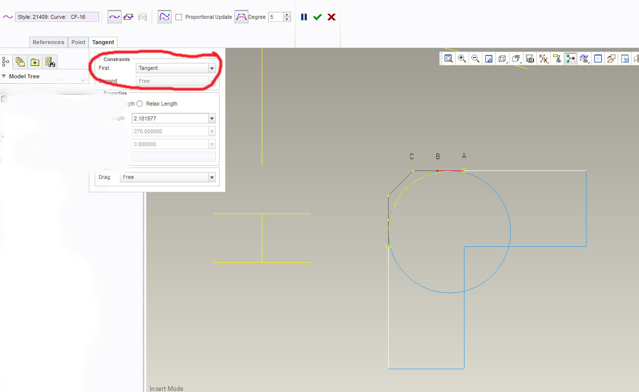
Hi Bernie, that is the exact method I am using. My issues are these though.
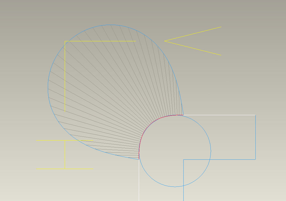
You can choose between curvature or tangent of the end point. If you switch control points on (when you are editing the ISDX curve next to where you choose number of degrees) you get even more control. I attached a screen shot to help explain. I can only move points B and C independantly if the ends are tangent, if the ends are curvature B and C move together. When I look at the curvature graph (shown in a screen grab) and I keep the points at default but flip between curvature and tangent I see no difference. If I move point B closer to point C when the end is tangent I get a nicer curvature analysis (it gradually decreses to zero) on the ends. What I find strange is that this is a characteristic of a C2 curve but I can only achieve this with tangent ends not curvature ones?
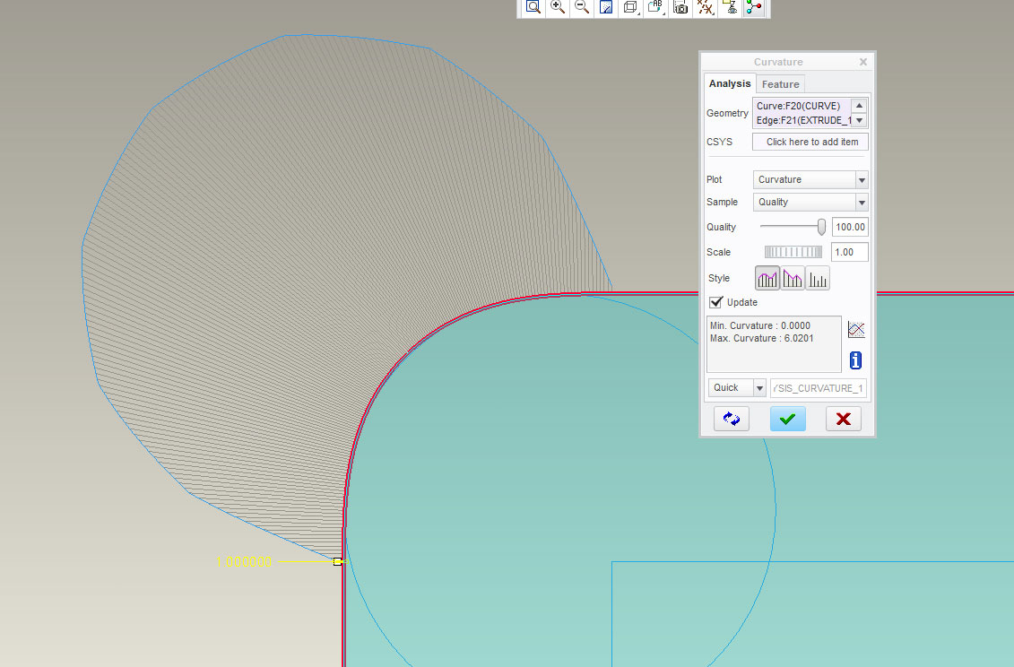
Another issue I am having is that when I extrude this curve my curvature analysis gets messed up. It looks stepped and the ends no longer go to zero (see screenshot). This happens if I copy the curve too. Basically whatever I do to that curve loses it's nice curvature.
Any ideas on this?!
Apr 01, 2014
11:10 PM
- Mark as New
- Bookmark
- Subscribe
- Mute
- Subscribe to RSS Feed
- Permalink
- Notify Moderator
Please log in to access translation
Apr 01, 2014
11:10 PM
Racheal,
For this, I would refer you back to Greg's comments. I think what your
seeing is intended functionality. I can't speak for right or wrong, but
rather, it is what it is and (as far as I can remember) has always been. I
think it just boils down to the math that controls Tangency conditions vs
Curvature conditions.
Then, I will also reference Greg's comments on "Personal Preference".
Personally, I don't mess with the ISDX control points. To me, they just
"muddy the water". I try to keep it as simple as I can and really only mess
with Tangent vs Curvature end control, Trim lengths, and stretch values as
stated in my earlier post. Overall, I have been very happy (and very
successful) with that method.
As for your other issue, (someone please correct me if I'm wrong...) I
don't know that Extrude features have ever been able to maintain Curvature.
IMHO... If I'm working a project that is styled enough that I need to
create Curvature construction features, then its also worth me taking the
time to build proper Boundary surfaces so that I can control all of the
edge conditions.
If I'm working something that is not so styled then I stick to extrudes and
radii. --- or maybe Conic Radii with a Stretch 🙂
Good Luck
Bernie
Bernie Gruman
Owner / Designer / Builder
www.GrumanCreations.com
Apr 02, 2014
11:16 AM
- Mark as New
- Bookmark
- Subscribe
- Mute
- Subscribe to RSS Feed
- Permalink
- Notify Moderator
Please log in to access translation
Apr 02, 2014
11:16 AM
R R,
What you are describing with the control points is how 3 (or is it 5)degree curves controls act when restricted to C2... For the math to work.If you want more ability to have the ends curvature you need either a higher degree curve (in Creo 2 Style) or another point on the curve.
Theoretically you can make a curve C1 or C2 without the end constraint being set as such. You'd just have to get those control points in the exact right place by manually moving them. When you add the constraint Creo automatically sets them in the right place. And when you go to move them, Creo follow the constraint rules you just set.
So, one advantage of the Style curve is the ability to increase the degree of curve, which I believe is unique to the Style tool and not available in sketch or datum curve.
You analysis being blocky is strange, I've never witnessed this behavior. I suspect weirdness in the analysis tool.
Too bad you're not on Creo 2 where you can just create a G2 fillet.
Hope it helps!
-Vaughn McDaniel
Apr 02, 2014
11:27 AM
- Mark as New
- Bookmark
- Subscribe
- Mute
- Subscribe to RSS Feed
- Permalink
- Notify Moderator
Please log in to access translation
Apr 02, 2014
11:27 AM
"As for your other issue, (someone please correct me if I'm wrong...) I
don't know that Extrude features have ever been able to maintain Curvature.
IMHO...As for your other issue, (someone please correct me if I'm wrong...) I
don't know that Extrude features have ever been able to maintain Curvature.
IMHO... "
Here's what's going on.
After you select "Project" and pick the ISDX curve, you can see the "Use Edge" constraint on the curve.
It looks like a small backwards "S". Toggle until you can select just this constraint, then delete it.
You can see that the curve created in sketcher is not an exact duplicate but really a spline with many control points approximating the original curve. This is why the curvature analysis of your extrude is looking so rough.
If you want more accuracy, you have to build the surface in ISDX or as a boundary blend as Bernie says.
Or if you really have to make it an extrude, then you're going to have tosketch a spline and constrain the polygon.
Apr 02, 2014
11:50 AM
- Mark as New
- Bookmark
- Subscribe
- Mute
- Subscribe to RSS Feed
- Permalink
- Notify Moderator
Please log in to access translation
Apr 02, 2014
11:50 AM
Hi Greg that's a really helpful explanation thanks!
I think I am understanding more. I have one more question. Is there a way
to select and drag 2 control points in ISDX proportionally? (image C in my
screen shot and another point C on the vertical section). I'm spending a
lot of time fiddling with numbers!
Anyone know of any really advanced tutorials on C2 curves/surfaces ISDX?
Apr 02, 2014
11:53 AM
- Mark as New
- Bookmark
- Subscribe
- Mute
- Subscribe to RSS Feed
- Permalink
- Notify Moderator
Please log in to access translation
Apr 02, 2014
11:53 AM
FWIW: Once I learned about Conic curves and how to use them they are my preference in defining and control complex curves which might have been created with splines or in ISDX in a reference part. Granted I have not been creating critical automotive styling, but for some rather advanced complex shapes on consumer products I think they are fine. When needed I will use the initial designers part as a "template" to define my conics to "match" or very closely simulate and then the curves are easier to change and control later. It does take some getting use to to conics. When I was a Pro/E neophyte I wondered why conics would be used, but after designing some plastic parts for consumer products I saw the light.
Mark A. Peterson
Design Engineer
Varel International
lxandr@sbcgolbal.net
Mark A. Peterson
Design Engineer
Varel International
lxandr@sbcgolbal.net
Apr 02, 2014
01:27 PM
- Mark as New
- Bookmark
- Subscribe
- Mute
- Subscribe to RSS Feed
- Permalink
- Notify Moderator
Please log in to access translation
Apr 02, 2014
01:27 PM
Lots of good nuggets in allthe posts.
RR, keep in mind that adding all the "control" mentioned in other's posts you can run the risk of doing a couple things. 1. the complexity of the math gets intense by increasing curve order (I.E. knots in the curve) and can increase regen time and file size. Not necessarily a bad thing but you will have to watch it over time that your model does not get too heavy. 2. Even though you are gaining knowledge and skill, the next person may not be as versed in your, or the others,techniques and mess things up badly. And they can do it without knowing it. Tweaking, stretching and dragging nodes, as Bernie stated, gets a little messy and is essentially "hidden" and can be really subjective to the Designer's eye. If you are creating a part that will be touched by others in the future...try to keep it simple and as mathematically explicitas you can.
Be wise in the techniques you use. If you aredeveloping Class A surfaces thatare stamped and/or formed metal that will be chromed or painted, then yes, you indeed need to bring out the big guns and use all the control needed to get sweet surfaces.However, molded plastic is another story and is a subjective call. IMHO, 95% of products molded do not need to be Class A....just really pretty.
Apr 02, 2014
01:58 PM
- Mark as New
- Bookmark
- Subscribe
- Mute
- Subscribe to RSS Feed
- Permalink
- Notify Moderator
Please log in to access translation
Apr 02, 2014
01:58 PM
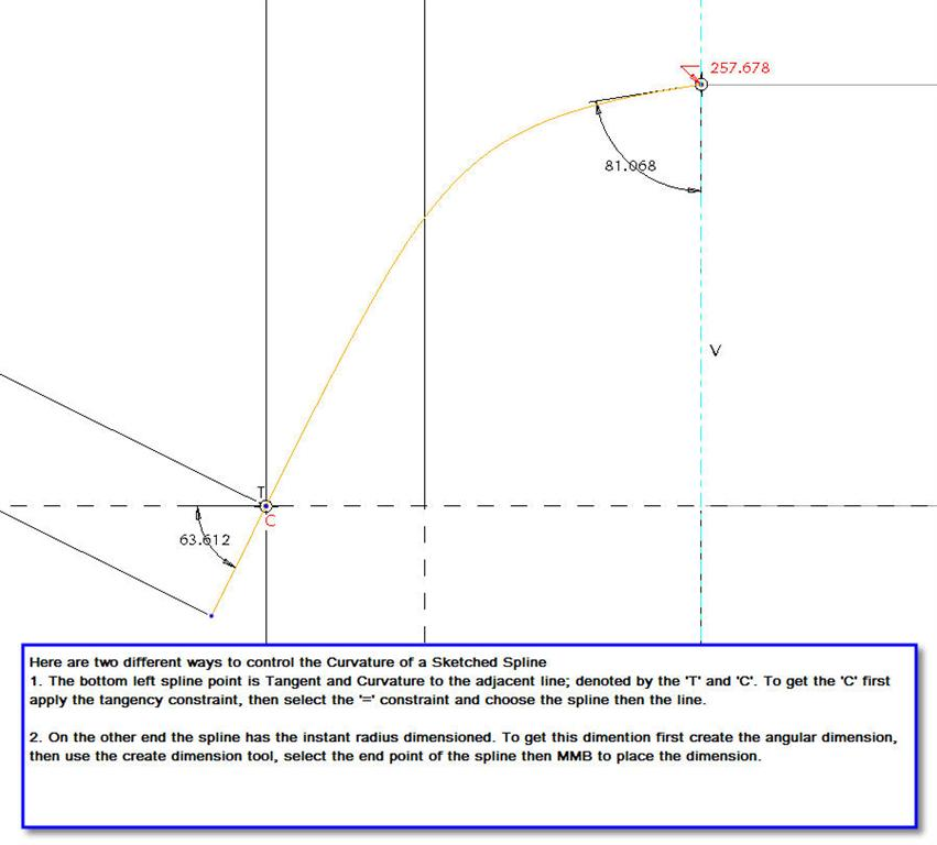
It took me years to learn about how to make a sketched spline curvature in sketch. So, for anyone out there, this image shows how to do so.
Apr 03, 2014
04:01 AM
- Mark as New
- Bookmark
- Subscribe
- Mute
- Subscribe to RSS Feed
- Permalink
- Notify Moderator
Please log in to access translation
Apr 03, 2014
04:01 AM
Vaughn,
Probably a daft question, but how did you create the angular dimension?
John
Apr 03, 2014
04:20 AM
- Mark as New
- Bookmark
- Subscribe
- Mute
- Subscribe to RSS Feed
- Permalink
- Notify Moderator
Please log in to access translation
Apr 03, 2014
04:20 AM
John,
To create the angle dimension:
1. Select the spline.
2. Select the spline end point.
3. Select the construction line (or the reference that you want the dimension created between) MMB to place.
Vaughn - Sorry to highjack your posting.
Steve Birman
Chief Designer
Stryker Medical
3800 East Centre Ave.
Portage, Michigan 49002
Apr 03, 2014
03:23 PM
- Mark as New
- Bookmark
- Subscribe
- Mute
- Subscribe to RSS Feed
- Permalink
- Notify Moderator
Please log in to access translation
Apr 03, 2014
03:23 PM
"Anyone know of any really advanced tutorials on C2 curves/surfaces ISDX?"
You have to go over to Design-Engine.
Bart will teach you everything you need to know.
They teach ISDX and also Rhino and Alias, so they know everything about the underlying definitions of curves that you won't find out from any other Creo-specific classes or tutorials


