
Turn on suggestions
Auto-suggest helps you quickly narrow down your search results by suggesting possible matches as you type.
Showing results for
Please log in to access translation
Turn on suggestions
Auto-suggest helps you quickly narrow down your search results by suggesting possible matches as you type.
Showing results for
- Community
- Creo+ and Creo Parametric
- 3D Part & Assembly Design
- Applying torque in Simulate
Translate the entire conversation x
Please log in to access translation
Options
- Subscribe to RSS Feed
- Mark Topic as New
- Mark Topic as Read
- Float this Topic for Current User
- Bookmark
- Subscribe
- Mute
- Printer Friendly Page
Applying torque in Simulate
Sep 16, 2015
10:29 AM
- Mark as New
- Bookmark
- Subscribe
- Mute
- Subscribe to RSS Feed
- Permalink
- Notify Moderator
Please log in to access translation
Sep 16, 2015
10:29 AM
Applying torque in Simulate
Hello All,
I am a fairly inexperienced Simulate user and I am trying to simulate a torsion input through a rectangular keyway on a part I have designed. I am familiar with the fact that moments need to be applied using the 'Total load at Point' option...but I am unable to actually make this happen in my model correctly. I would like to apply a moment of 5100 in-lbs to one of the keyway surfaces.
I created a cylindrical coordinate system and a point along the rotational axis in an effort to get this thing to run...but I wasn't able to make it work.
Any suggestions?
Please see attached files. The file named T7_TURNTABLE_SIM.PRT is my simulate model.
Thanks,
Mark Evans
This thread is inactive and closed by the PTC Community Management Team. If you would like to provide a reply and re-open this thread, please notify the moderator and reference the thread. You may also use "Start a topic" button to ask a new question. Please be sure to include what version of the PTC product you are using so another community member knowledgeable about your version may be able to assist.
Labels:
- Labels:
-
General
3 REPLIES 3
Sep 16, 2015
10:55 AM
- Mark as New
- Bookmark
- Subscribe
- Mute
- Subscribe to RSS Feed
- Permalink
- Notify Moderator
Please log in to access translation
Sep 16, 2015
10:55 AM
Hi Mark,
A screenshot would be helpful, to save us downloading and opening your models... but I would suggest applying the load as a force or pressure to the side of the keyway (or possibly as a force on the inner edge of the keyway). If you apply a moment, it will try to actually twist the face of the keyway - use the Preview button to see what it's doing.
You should also then apply an equal and opposite reaction on one side of the bore - think about the free body diagram of the system. Use Review Total Load to ensure that the keyway load gives you the correct resultant torque.
Depending on which stresses you're interested in, you may find that you need to model an assembly of hub, key and shaft, and run a contact analysis to get meaningful results. Make sure that the clearances between the key and each slot are representative of the real fits!
Also, why have you created a 'dumb' copy of the model to set up the Simulate run?
Sep 17, 2015
02:52 AM
- Mark as New
- Bookmark
- Subscribe
- Mute
- Subscribe to RSS Feed
- Permalink
- Notify Moderator
Please log in to access translation
Sep 17, 2015
02:52 AM
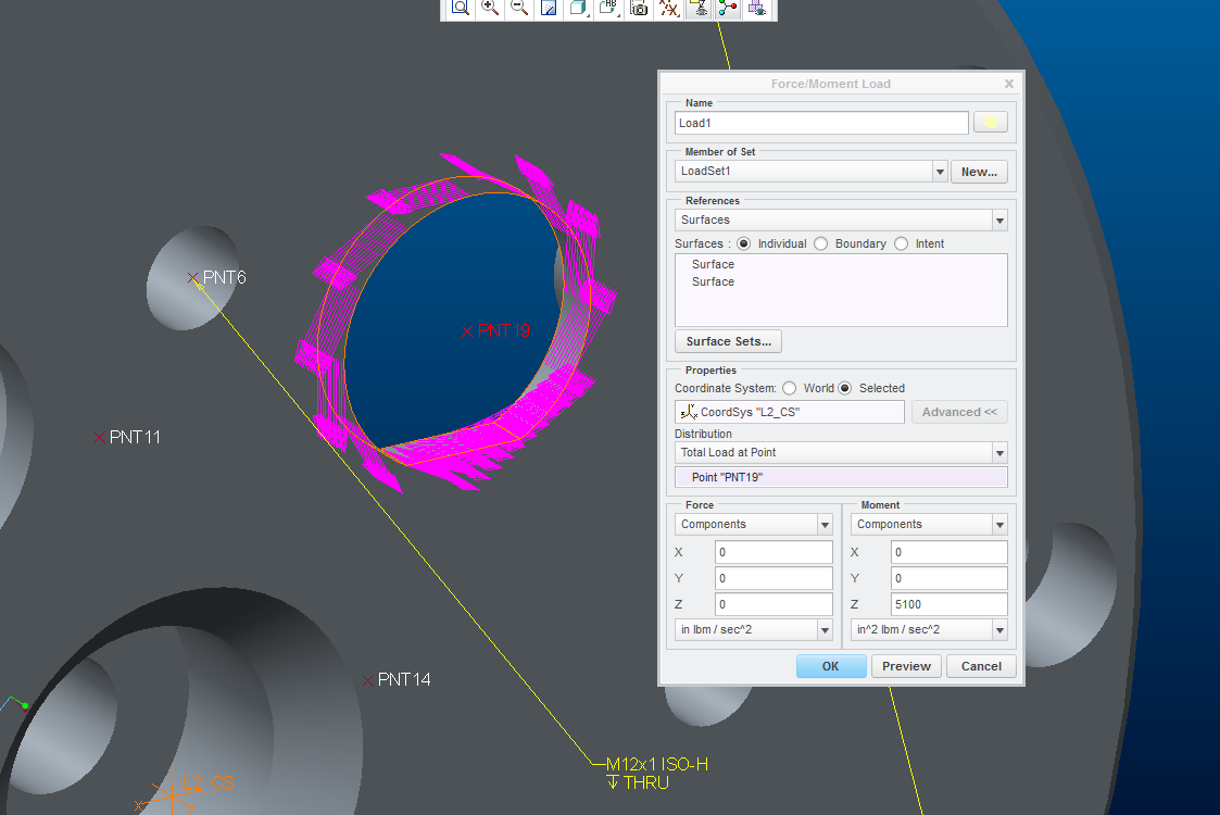
Here's how I did it:
-Create a datum point at the centre of the keyway hole.
-Create a "Total load at point" moment, using the point you just created
-Enter 5100 in the positive Z direction for the MOMENT...
-Click "preview"
Notes:
-The "total load at point" option provides an often good enough approximation of the load distribution. For a more accurate load distribution, add the tightening tool (assembly mode) and create contact interfaces between tool and keyway hole surfaces, run a contact analysis. Refine the mesh at the contact surfaces.
-The rigid constraints at the holes may also be a good enough approximation of how the force is transmitted through the structure. Once again, for a more accurate analysis, the adjoining component should be modeled, typically with fasteners...
-Your model contains a number of reentrant corners where the calculated stresses will not be accurate. Infinitely sharp corners like this do not exist in reality; there is always a radius of some size and consequently a finite stress level. Nonetheless, your model can still be used for analysis even if local stresses are high. Pressure vessel codes such as ASME provide techniques to use linearized stress results (this is also implemented in Creo, although in older releases it's not very user friendly) for dimensioning, that will allow small stress peaks above yield stress, as long as the peak linearized stress is low enough. There are also similar techniques developed for dimensioning welds, that can be used in cases where you have a small stress peak at the location of the weld.
Good luck with your work...
B.R. Mats L
Sep 21, 2015
03:51 AM
- Mark as New
- Bookmark
- Subscribe
- Mute
- Subscribe to RSS Feed
- Permalink
- Notify Moderator
Please log in to access translation
Sep 21, 2015
03:51 AM
Note;
- The location of the point in total load at point is irrelevant, the rotation axis will be the center of the surface you transfer the load to.
- When this surface is not cylindrical/symmetrical, you can use 'total bearing load at point'.


