
Turn on suggestions
Auto-suggest helps you quickly narrow down your search results by suggesting possible matches as you type.
Showing results for
Please log in to access translation
Turn on suggestions
Auto-suggest helps you quickly narrow down your search results by suggesting possible matches as you type.
Showing results for
Community Tip - You can subscribe to a forum, label or individual post and receive email notifications when someone posts a new topic or reply. Learn more! X
- Community
- Creo+ and Creo Parametric
- 3D Part & Assembly Design
- Re: Assembly components defined by "Fix" constrain...
Translate the entire conversation x
Please log in to access translation
Options
- Subscribe to RSS Feed
- Mark Topic as New
- Mark Topic as Read
- Float this Topic for Current User
- Bookmark
- Subscribe
- Mute
- Printer Friendly Page
Assembly components defined by "Fix" constraint
Oct 08, 2015
02:13 PM
- Mark as New
- Bookmark
- Subscribe
- Mute
- Subscribe to RSS Feed
- Permalink
- Notify Moderator
Please log in to access translation
Oct 08, 2015
02:13 PM
Assembly components defined by "Fix" constraint
Is there a quick way to display which components within an assembly are constrained using the "Fix" option?
I am updating a large assembly and have found some components are fixed into position. I have redefined the components I have stumbled upon as fixed, but would like to verify that the rest of the assembly is clear of fixed components. I realize I could check the definition of each component, but I'd prefer a quicker method than doing so for 150+ items individually. Thanks.
This thread is inactive and closed by the PTC Community Management Team. If you would like to provide a reply and re-open this thread, please notify the moderator and reference the thread. You may also use "Start a topic" button to ask a new question. Please be sure to include what version of the PTC product you are using so another community member knowledgeable about your version may be able to assist.
Solved! Go to Solution.
Labels:
- Labels:
-
General
- Tags:
- constraint
- fix
- search
ACCEPTED SOLUTION
Accepted Solutions
Oct 22, 2015
10:03 AM
- Mark as New
- Bookmark
- Subscribe
- Mute
- Subscribe to RSS Feed
- Permalink
- Notify Moderator
Please log in to access translation
Oct 22, 2015
10:03 AM
Open Search Tool (Ctrl+F), Look for = Components / Status / Attributes = is equal to = Fixed Placement ; Find.
Do not forget to check "include submodels".
Another place to do the same even faster : above Model Tree "quick search" drop button, select "Fixed Placement" query - done.
Hope this helps ...
- Vlad
15 REPLIES 15
Oct 08, 2015
02:24 PM
- Mark as New
- Bookmark
- Subscribe
- Mute
- Subscribe to RSS Feed
- Permalink
- Notify Moderator
Please log in to access translation
Oct 08, 2015
02:24 PM
I don't know of a direct way to do it but one method is to use the model tree. (creo 2)
1. Set the model tree to show only placement folders.
2. Expand all on the model tree.
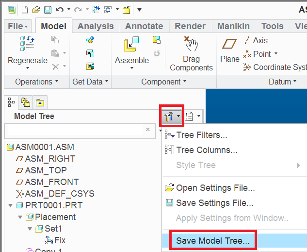
3. Save the model tree (not the settings but the text out)
4. Search the text file for the word "FIX"
You can automate steps 1-3 with a mapkey if you find yourself doing this over and over.
Oct 09, 2015
02:10 AM
- Mark as New
- Bookmark
- Subscribe
- Mute
- Subscribe to RSS Feed
- Permalink
- Notify Moderator
Please log in to access translation
Oct 09, 2015
02:10 AM
Expand All
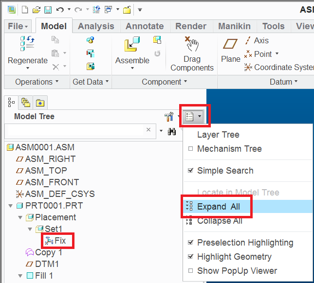
Save
MH
Martin Hanák
Oct 22, 2015
10:03 AM
- Mark as New
- Bookmark
- Subscribe
- Mute
- Subscribe to RSS Feed
- Permalink
- Notify Moderator
Please log in to access translation
Oct 22, 2015
10:03 AM
Open Search Tool (Ctrl+F), Look for = Components / Status / Attributes = is equal to = Fixed Placement ; Find.
Do not forget to check "include submodels".
Another place to do the same even faster : above Model Tree "quick search" drop button, select "Fixed Placement" query - done.
Hope this helps ...
- Vlad
Oct 22, 2015
10:21 AM
- Mark as New
- Bookmark
- Subscribe
- Mute
- Subscribe to RSS Feed
- Permalink
- Notify Moderator
Please log in to access translation
Oct 22, 2015
10:21 AM
I don't get "Fixed Placement" in either method in Creo 2 M170. Are these new for Creo 3?
Oct 22, 2015
11:00 AM
- Mark as New
- Bookmark
- Subscribe
- Mute
- Subscribe to RSS Feed
- Permalink
- Notify Moderator
Please log in to access translation
Oct 22, 2015
11:00 AM
Yep, Creo3 - sorry for not mentioning this.
Oct 22, 2015
11:02 AM
- Mark as New
- Bookmark
- Subscribe
- Mute
- Subscribe to RSS Feed
- Permalink
- Notify Moderator
Please log in to access translation
Oct 22, 2015
11:02 AM
Creo 2 and before - only the way martin suggested above, filter / dump tree and search for "Fix" ...
Mar 31, 2016
05:48 PM
- Mark as New
- Bookmark
- Subscribe
- Mute
- Subscribe to RSS Feed
- Permalink
- Notify Moderator
Please log in to access translation
Mar 31, 2016
05:48 PM
Not to hijack Nathan's original question, but are there issues using "Fix"? I am guilty of using it on occasion. I hear it may exacerbate my drawing views shifting, and some other problems. Obviously it isn't the best way to assemble a component, but if it's a small component, and good assembly parameters don't exist it is a very convenient method of assembly. Just looking to do things correctly, and avoid problems.
Thanks.
Bruce
Apr 01, 2016
07:11 AM
- Mark as New
- Bookmark
- Subscribe
- Mute
- Subscribe to RSS Feed
- Permalink
- Notify Moderator
Please log in to access translation
Apr 01, 2016
07:11 AM
Fix is simply an offset coordinate system constraint. Once you've added the fix constraint and you edit the component, you get x, y, z dimensions and angles. It's just another tool in the toolbox.
Apr 06, 2016
07:21 PM
- Mark as New
- Bookmark
- Subscribe
- Mute
- Subscribe to RSS Feed
- Permalink
- Notify Moderator
Please log in to access translation
Apr 06, 2016
07:21 PM
In Creo 2 I see no option besides deleting the Fix constraint and moving the part and refixing. Is this a Creo 3 option? I know if I leave a component Packaged I can drag the component or rotate the component, but I don't recall ever seeing Edit showing offsets and angles. Easy to miss if it's there because I haven't had a desire to use Fix in the last 2 decades.
Apr 07, 2016
08:54 AM
- Mark as New
- Bookmark
- Subscribe
- Mute
- Subscribe to RSS Feed
- Permalink
- Notify Moderator
Please log in to access translation
Apr 07, 2016
08:54 AM
Component is placed using fix.
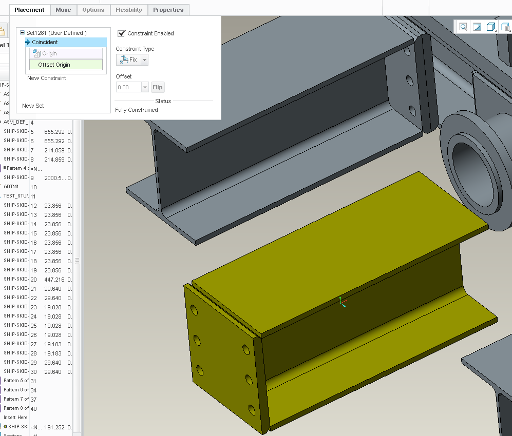
Done out of the assemble component dialog.
Select component, right mouse EDIT and you get 3 linear dimensions and 3 angle dimension (6 degrees). The angles are shown at the assembly coord sys and the dimensions are show to the component coord sys.
Fix is simply and offset coord sys constraint. Works great for some situations.
Apr 07, 2016
08:55 AM
- Mark as New
- Bookmark
- Subscribe
- Mute
- Subscribe to RSS Feed
- Permalink
- Notify Moderator
Please log in to access translation
Apr 07, 2016
08:55 AM
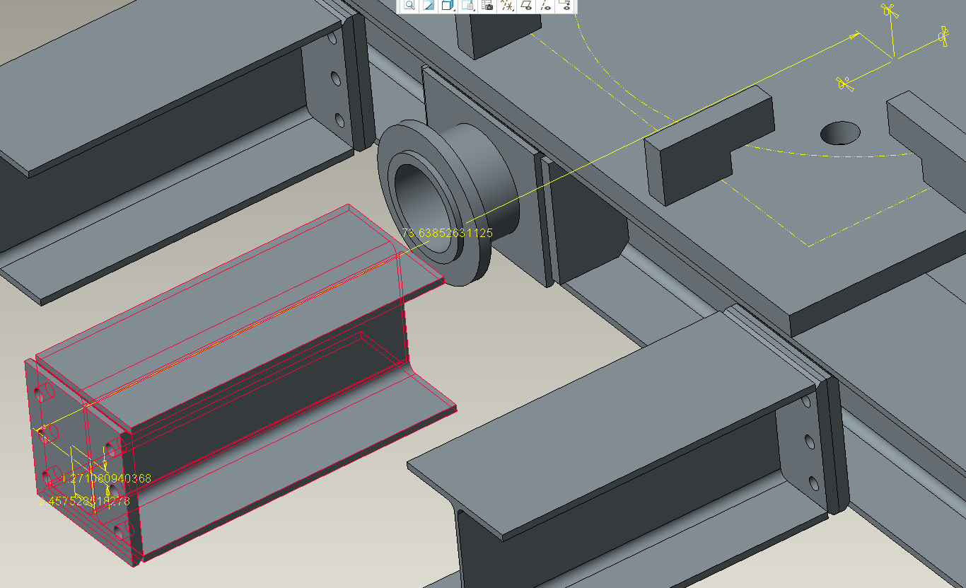
Oh and don't steal my big dumb steel design. I worked for several minutes creating that masterpiece yesterday.
Mar 31, 2016
07:19 PM
- Mark as New
- Bookmark
- Subscribe
- Mute
- Subscribe to RSS Feed
- Permalink
- Notify Moderator
Please log in to access translation
Mar 31, 2016
07:19 PM
For me, a decent model is a peek into the future and a fixed component doesn't give an accurate picture of reasonable futures. It's only a problem if there are problems that could have been found before the factory floor or in use.
One can fall back to using vertices/point on surface constraints to get even obnoxious parts to assemble, but it's better to have models that have reasonable features, such as axes in the centers of slots (or axes that are dimensioned from the center of slots to match how slots are normally used.)
Apr 06, 2016
01:04 PM
- Mark as New
- Bookmark
- Subscribe
- Mute
- Subscribe to RSS Feed
- Permalink
- Notify Moderator
Please log in to access translation
Apr 06, 2016
01:04 PM
I really want this thread to be marked as Answered, since it contains very useful information.
Unfortunately the full answer is distributed over three posts:
- Best Solution steps
- Best Solution is only in Creo 3.0
- Best workaround for older versions
-> Since I can choose only one, I am marking the best solution as Correct Answer, to avoid Creo 3.0 users going for the more cumbersome workaround, because they overlook the Creo 3.0 solution (hoping users of older versions will go through the whole thread anyway, when they notice the best solution doesn't work for them)
Apr 06, 2016
01:28 PM
- Mark as New
- Bookmark
- Subscribe
- Mute
- Subscribe to RSS Feed
- Permalink
- Notify Moderator
Please log in to access translation
Apr 06, 2016
01:28 PM
In the future, you could create a reply with a link to the each of the 3 posts with the best answers and then mark your reply as the answer. Then all three get linked in the top of the thread.
Apr 07, 2016
03:26 AM
- Mark as New
- Bookmark
- Subscribe
- Mute
- Subscribe to RSS Feed
- Permalink
- Notify Moderator
Please log in to access translation
Apr 07, 2016
03:26 AM
Seems like a good advice to me.
Thank you Doug, I'll consider this in future!


