Community Tip - Need to share some code when posting a question or reply? Make sure to use the "Insert code sample" menu option. Learn more! X
- Community
- Creo+ and Creo Parametric
- 3D Part & Assembly Design
- Axis lines in .drw format
- Subscribe to RSS Feed
- Mark Topic as New
- Mark Topic as Read
- Float this Topic for Current User
- Bookmark
- Subscribe
- Mute
- Printer Friendly Page
Axis lines in .drw format
- Mark as New
- Bookmark
- Subscribe
- Mute
- Subscribe to RSS Feed
- Permalink
- Notify Moderator
Axis lines in .drw format
Hi all,
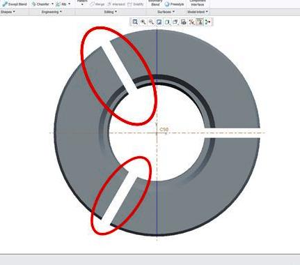
I'm creating a wedge with three slits. I cant seem to figure out how to get my axis lines to show in my drawing view. How do I get these two angled axis lines (on the left side) to show on my drawing?

This thread is inactive and closed by the PTC Community Management Team. If you would like to provide a reply and re-open this thread, please notify the moderator and reference the thread. You may also use "Start a topic" button to ask a new question. Please be sure to include what version of the PTC product you are using so another community member knowledgeable about your version may be able to assist.
Solved! Go to Solution.
- Labels:
-
General
Accepted Solutions
- Mark as New
- Bookmark
- Subscribe
- Mute
- Subscribe to RSS Feed
- Permalink
- Notify Moderator
Hello Kaci.
There is no simple way but generally this is done in the model by creating a datum axis. You could do this with a sketch by defining a geometry axes, but sketches tend to hide if you do other things with them. You could also do the slots as extrudes from the center of the part and use a geometry point to generate an axis. Obviously no shortage of creating said datum axis.
In the drawing you can also create a centerline font sketched line, parametric even. But this often ends up being the path of greatest resistance.
When I create models, I very much have to manage how features will be displayed in drawings. It is not uncommon to have a few additional datum and sketch features at the end of a part only to satisfy drawing needs. Of course, anyone sustaining the model just blows them away being "efficient" only to understand why you added them in the 1st place when the drawing is opened and things are missing, -if- anyone bothers to notice.


