Community Tip - New to the community? Learn how to post a question and get help from PTC and industry experts! X
- Community
- Creo+ and Creo Parametric
- 3D Part & Assembly Design
- Re: Beam Idealization
- Subscribe to RSS Feed
- Mark Topic as New
- Mark Topic as Read
- Float this Topic for Current User
- Bookmark
- Subscribe
- Mute
- Printer Friendly Page
Beam Idealization
- Mark as New
- Bookmark
- Subscribe
- Mute
- Subscribe to RSS Feed
- Permalink
- Notify Moderator
Beam Idealization
In the Creo Simulate Help Center it says the use of beam idealizations is only valid for a ratio of beam height to its length of up to 1/10.
I would like to simulate a part which has a ratio of 4/10. Simulating the part as a solid is not an option.
How does that "invalid" ratio influence the simulation results?
I would also like to know how many nodes/elements Creo Simulate creates on each beam idealization and if this is variable.
Any help is greatly appreciated.
Solved! Go to Solution.
- Labels:
-
General
Accepted Solutions
- Mark as New
- Bookmark
- Subscribe
- Mute
- Subscribe to RSS Feed
- Permalink
- Notify Moderator
- Mark as New
- Bookmark
- Subscribe
- Mute
- Subscribe to RSS Feed
- Permalink
- Notify Moderator
- Mark as New
- Bookmark
- Subscribe
- Mute
- Subscribe to RSS Feed
- Permalink
- Notify Moderator
Thank you very much for your fast answer, Paul.
I hope I interpret your model correctly since I see only a difference in the max. deformation value of about +2,3 %.
I attached a sketch of my use case. Is the deformation difference the only deviation resulting from the use of the beam idealization? If yes, that would cause point A and B to displace a little more than they should but due to their identical behaviour the long beam would undergo the same load, wouldn't it?
Best regards
Patrick
- Mark as New
- Bookmark
- Subscribe
- Mute
- Subscribe to RSS Feed
- Permalink
- Notify Moderator
- Mark as New
- Bookmark
- Subscribe
- Mute
- Subscribe to RSS Feed
- Permalink
- Notify Moderator
Again, thanks very very much for your very helpful model!
I hope that this is the last time I have to ask a question concering this topic.
I see that in this case the displacement difference of a solid and a beam model is huge.
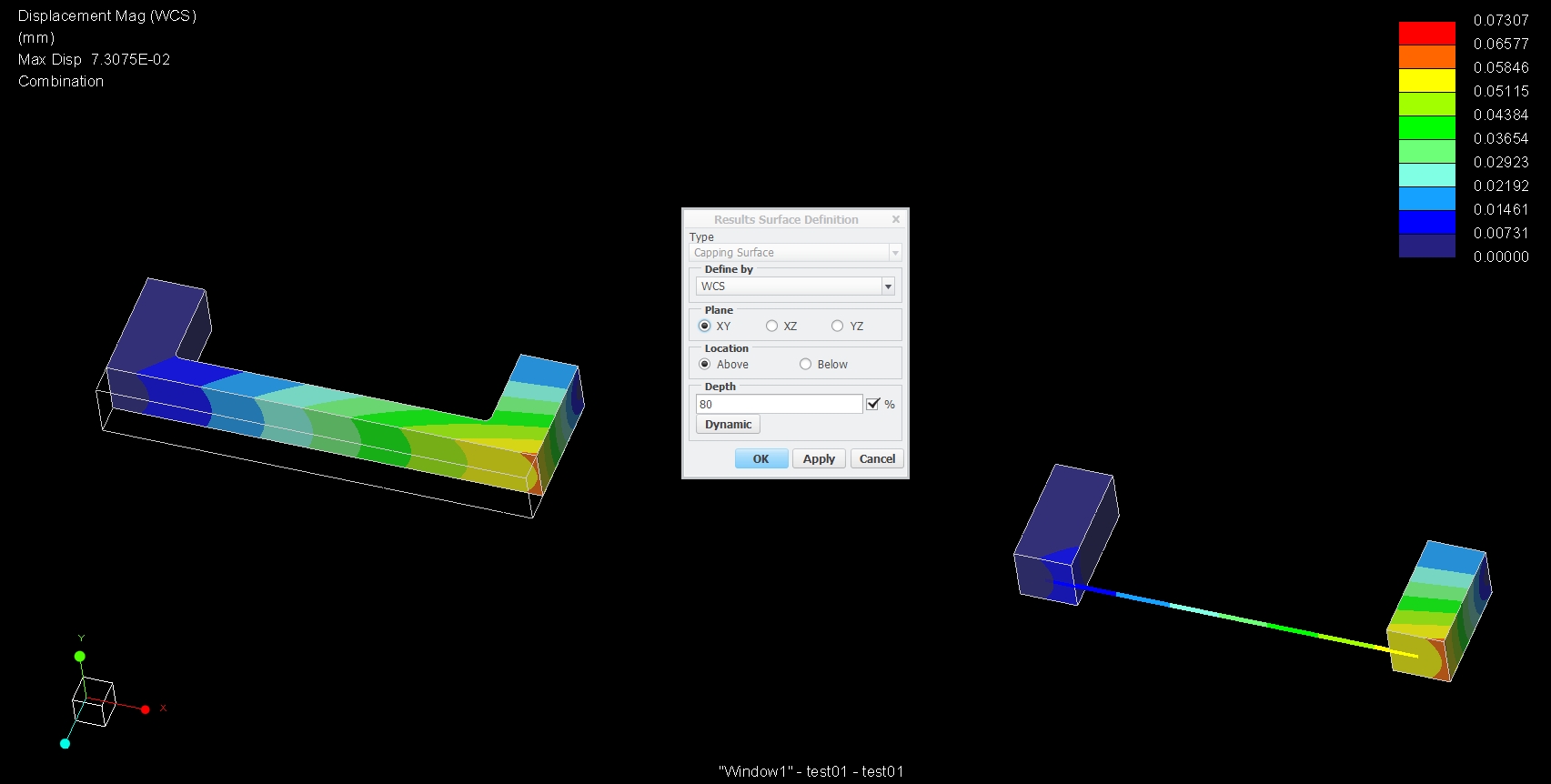
Due to the fact that I have lots of these c-profiles connected to each other, I want to use the beams at least for the longest beam. (attached file: example_02)
I attached a comparison between a solid, beam and combination of both (example_01). In this comparison there is huge displacement difference of the mixed beam-solid model and the solid model. But this time the ratio of beam height to its length is valid according to Timoshenko beam theory.
The only possible blind spot I can imagine is the connection between the beam and the solid or is there another mistake I don't recognize?
I would really appreciate your help.
Best regards
Patrick
- Mark as New
- Bookmark
- Subscribe
- Mute
- Subscribe to RSS Feed
- Permalink
- Notify Moderator
- Mark as New
- Bookmark
- Subscribe
- Mute
- Subscribe to RSS Feed
- Permalink
- Notify Moderator


