
Turn on suggestions
Auto-suggest helps you quickly narrow down your search results by suggesting possible matches as you type.
Showing results for
Please log in to access translation
Turn on suggestions
Auto-suggest helps you quickly narrow down your search results by suggesting possible matches as you type.
Showing results for
Community Tip - Learn all about PTC Community Badges. Engage with PTC and see how many you can earn! X
- Community
- Creo+ and Creo Parametric
- 3D Part & Assembly Design
- Bend line manipulation in drawings question
Translate the entire conversation x
Please log in to access translation
Options
- Subscribe to RSS Feed
- Mark Topic as New
- Mark Topic as Read
- Float this Topic for Current User
- Bookmark
- Subscribe
- Mute
- Printer Friendly Page
Bend line manipulation in drawings question
Jun 17, 2015
05:58 PM
- Mark as New
- Bookmark
- Subscribe
- Mute
- Subscribe to RSS Feed
- Permalink
- Notify Moderator
Please log in to access translation
Jun 17, 2015
05:58 PM
Bend line manipulation in drawings question
HI,
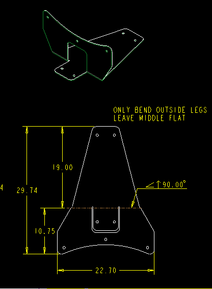
I have a part that you can see below. I created 2 flanges and joined them together with a planar feature. It works great in the model. Now when I am creating the print, the bend line is a single bend line across the part, which makes sense since it really should be bent at the same time. However, I want to delete the part of the line that is going over the part that is not being bent because I'm pretty sure that at some point, one of my brake operators is going to see the line all of the way across and bend up the flat part too. I can't get two bend lines to show up, and I can't get the sketch features to snap to the line in the drawing. Any ideas on how to make two separate lines in the drawing?
Thanks,
Brandon
This thread is inactive and closed by the PTC Community Management Team. If you would like to provide a reply and re-open this thread, please notify the moderator and reference the thread. You may also use "Start a topic" button to ask a new question. Please be sure to include what version of the PTC product you are using so another community member knowledgeable about your version may be able to assist.
Solved! Go to Solution.
Labels:
- Labels:
-
General
ACCEPTED SOLUTION
Accepted Solutions
Jun 18, 2015
06:37 AM
- Mark as New
- Bookmark
- Subscribe
- Mute
- Subscribe to RSS Feed
- Permalink
- Notify Moderator
Please log in to access translation
Jun 18, 2015
06:37 AM
Can't you just use the "break" functionality in the drawing module? It's under "Annotate->Break", in Creo 2.0. You pick two points and the region between them is "blanked out". We use this all the time.
6 REPLIES 6
Jun 17, 2015
07:50 PM
- Mark as New
- Bookmark
- Subscribe
- Mute
- Subscribe to RSS Feed
- Permalink
- Notify Moderator
Please log in to access translation
Jun 17, 2015
07:50 PM
Not sure on the answer - will suggest you could also get the part back with only the little tab bent up, if they are able to ignore the note. Doesn't the trimetric head off this problem?
Jun 18, 2015
08:30 AM
- Mark as New
- Bookmark
- Subscribe
- Mute
- Subscribe to RSS Feed
- Permalink
- Notify Moderator
Please log in to access translation
Jun 18, 2015
08:30 AM
David Schenken wrote:
Doesn't the trimetric head off this problem?
You would think.................... experience shows otherwise enough to be worried about it.
Jun 18, 2015
03:25 AM
- Mark as New
- Bookmark
- Subscribe
- Mute
- Subscribe to RSS Feed
- Permalink
- Notify Moderator
Please log in to access translation
Jun 18, 2015
03:25 AM
Hello Brandon,
my solution is following:
Create a second datum axis THROUGH a flat feater bend axis.
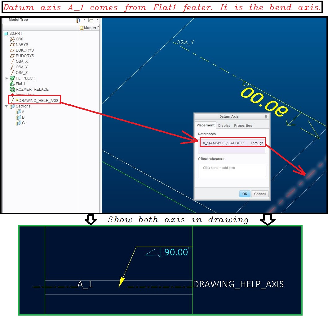
Hope it can helps you...
Jun 18, 2015
06:37 AM
- Mark as New
- Bookmark
- Subscribe
- Mute
- Subscribe to RSS Feed
- Permalink
- Notify Moderator
Please log in to access translation
Jun 18, 2015
06:37 AM
Can't you just use the "break" functionality in the drawing module? It's under "Annotate->Break", in Creo 2.0. You pick two points and the region between them is "blanked out". We use this all the time.
Jun 18, 2015
06:45 AM
- Mark as New
- Bookmark
- Subscribe
- Mute
- Subscribe to RSS Feed
- Permalink
- Notify Moderator
Please log in to access translation
Jun 18, 2015
06:45 AM
Some news for me  .
.
Your solution looks better than my own.
Jun 18, 2015
08:27 AM
- Mark as New
- Bookmark
- Subscribe
- Mute
- Subscribe to RSS Feed
- Permalink
- Notify Moderator
Please log in to access translation
Jun 18, 2015
08:27 AM
Awesome! that was exactly what I was looking for!


