Community Tip - Want the oppurtunity to discuss enhancements to PTC products? Join a working group! X
- Community
- Creo+ and Creo Parametric
- 3D Part & Assembly Design
- Re: Bilateral uneaual profile tolerance representa...
- Subscribe to RSS Feed
- Mark Topic as New
- Mark Topic as Read
- Float this Topic for Current User
- Bookmark
- Subscribe
- Mute
- Printer Friendly Page
Bilateral uneaual profile tolerance representation???
- Mark as New
- Bookmark
- Subscribe
- Mute
- Subscribe to RSS Feed
- Permalink
- Notify Moderator
Bilateral uneaual profile tolerance representation???
Hi Guys,
Can any body guide me to represent Bilateral uneaual profile tolerance???
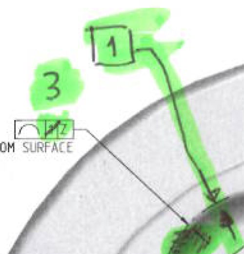
Attached is the requirement:) i.e. 3 mm is the total tolerance but I need 1mm outside & 2mm inside, attached is how we have to show but I don't know how to get the same in Pro/E.

Cheers,
Hari
This thread is inactive and closed by the PTC Community Management Team. If you would like to provide a reply and re-open this thread, please notify the moderator and reference the thread. You may also use "Start a topic" button to ask a new question. Please be sure to include what version of the PTC product you are using so another community member knowledgeable about your version may be able to assist.
- Labels:
-
Sheet Metal Design
- Mark as New
- Bookmark
- Subscribe
- Mute
- Subscribe to RSS Feed
- Permalink
- Notify Moderator
I can get a two point dimension to work like this and I have to break the leaders. If the feature is an arc, you can dimension across the two arcs and use "tangent" tangent" "Parallel" and select a feature parallel to the measurement. The I can either make the dimension basic or overwrite the dimension (@O) with @[1@].
It should be easier, and maybe it is, but that is what I was able to do quickly.
On two arcs, I was also able to use "Concentric" but you have little control over the orientation.
- Mark as New
- Bookmark
- Subscribe
- Mute
- Subscribe to RSS Feed
- Permalink
- Notify Moderator
Hi Antonius,
Thanks for your suggestion, but I was looking for something inbuilt option in ProE if there is any???
Hari
- Mark as New
- Bookmark
- Subscribe
- Mute
- Subscribe to RSS Feed
- Permalink
- Notify Moderator
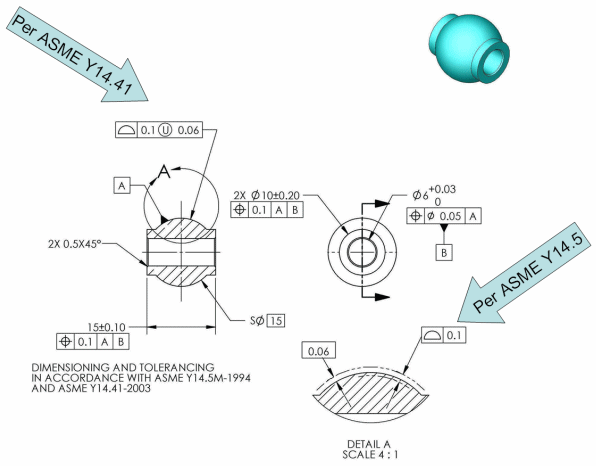
These are valid Variations:

And by creating a model sketch, you can get this:
I don't know of any graphics enhancement in the GTOL module itself. It has to be created one way or another. Personally, I do not like curves in my part or assembly models as it seems to always get in the way in next level assemblies.
I do see the option for a great enhancement opportunity to properly attach the dimension depicted in the Y14.5 example. Sort of a hybrid radius/diameter dimension.
- Mark as New
- Bookmark
- Subscribe
- Mute
- Subscribe to RSS Feed
- Permalink
- Notify Moderator
On the Symbols tab of the GTOL dialog box check the ASME 14.41 option. I don't recall off hand but you may also need to set it in the drawing.dtl.


