
Turn on suggestions
Auto-suggest helps you quickly narrow down your search results by suggesting possible matches as you type.
Showing results for
Please log in to access translation
Turn on suggestions
Auto-suggest helps you quickly narrow down your search results by suggesting possible matches as you type.
Showing results for
Community Tip - You can subscribe to a forum, label or individual post and receive email notifications when someone posts a new topic or reply. Learn more! X
- Community
- Creo+ and Creo Parametric
- 3D Part & Assembly Design
- Bolt Circle Issues - Dimensions
Translate the entire conversation x
Please log in to access translation
Options
- Subscribe to RSS Feed
- Mark Topic as New
- Mark Topic as Read
- Float this Topic for Current User
- Bookmark
- Subscribe
- Mute
- Printer Friendly Page
Bolt Circle Issues - Dimensions
Aug 26, 2025
03:35 PM
- Mark as New
- Bookmark
- Subscribe
- Mute
- Subscribe to RSS Feed
- Permalink
- Notify Moderator
Please log in to access translation
Aug 26, 2025
03:35 PM
Bolt Circle Issues - Dimensions
Another day and another CREO issue 🙂
So, I'm starting to get into detailing parts in CREO 10. Just to clarify - I have used NX and SolidWorks before and never ran into this issue.
I wanted to dimension the part attached and use Bolt Circles for the two different holes. I tried using "Show Model Dims" and bring in the axis and dims. Well one feature was created using a circular pattern - and the other was two separate features (I did not create this model). I figured out how to display a circular centerline by changing drafting settings - but when I brought the dimension in it was a Radius. There was no way for me to change this to a Diameter. So, I decided to create my own sketches in the view and decided to just dimension to this directly. I'm sure people will say, "That's not how CREO works - you create in model and then bring in the model features/dims" Sure - but when it doesn't show what you actually want - I want to have other options/features to present the dimension how I want it. Well, when I placed the two Dimensions it doesn't scale to the drawing view. The 2.800 dia should be 0.560. The 2.500 dim should be 0.500 (as you can surmise - the scale of the view is 5X).. Why doesn't CREO scale secondary dimensions on sketched features??? When I click on physical geometry the dimension scales appropriately (which should be expected). Why does this happen - and is there a way to fix this?????
Thanks
Solved! Go to Solution.
Labels:
- Labels:
-
Assembly Design
ACCEPTED SOLUTION
Accepted Solutions
Aug 26, 2025
03:39 PM
- Mark as New
- Bookmark
- Subscribe
- Mute
- Subscribe to RSS Feed
- Permalink
- Notify Moderator
Please log in to access translation
Aug 26, 2025
03:39 PM
Ignore.
So I sketched the Bolt Circles on top of the view - but did not associate or link to that view. Once you do this then the dims scale. Trial and error - I learned. Thanks.
18 REPLIES 18
Aug 26, 2025
03:39 PM
- Mark as New
- Bookmark
- Subscribe
- Mute
- Subscribe to RSS Feed
- Permalink
- Notify Moderator
Please log in to access translation
Aug 26, 2025
03:39 PM
Ignore.
So I sketched the Bolt Circles on top of the view - but did not associate or link to that view. Once you do this then the dims scale. Trial and error - I learned. Thanks.
Aug 27, 2025
01:54 AM
- Mark as New
- Bookmark
- Subscribe
- Mute
- Subscribe to RSS Feed
- Permalink
- Notify Moderator
Please log in to access translation
Aug 27, 2025
01:54 AM
Hi,
just a note ... you can also create Sketch feature representinf bolt circle inside the model. and set its line style in drawing.
Martin Hanák
Aug 27, 2025
06:47 AM
- Mark as New
- Bookmark
- Subscribe
- Mute
- Subscribe to RSS Feed
- Permalink
- Notify Moderator
Please log in to access translation
Aug 27, 2025
06:47 AM
When you sketch things on a drawing view, they're just "there" unless you relate them to the view. If you don't relate them, you get the dimensional wrongness you experienced. Another thing that can happen is if you move that view, any drawn items in the view that are not related to the view will NOT be moved along with the view. They are "left behind". A very unpleasant experience, to be sure.
Sep 29, 2025
01:45 PM
- Mark as New
- Bookmark
- Subscribe
- Mute
- Subscribe to RSS Feed
- Permalink
- Notify Moderator
Please log in to access translation
Sep 29, 2025
01:45 PM
Ken, I tried this approach and it works as you states, relate BC to view and it follows and is dimensionable. However, it is not associative or parametric. If I edit the bolt circle in the model, it does not update in the drawing.
I have seen where there are several methods to create a dimensionable bolt circle reference line (circular centerline) that is dimensinable but none of the examples appear to maintain parametric function.
Any suggestion? Am I missing a step?
Sep 29, 2025
02:42 PM
- Mark as New
- Bookmark
- Subscribe
- Mute
- Subscribe to RSS Feed
- Permalink
- Notify Moderator
Please log in to access translation
Sep 29, 2025
02:42 PM
Relating a drawing sketched bolt circle to a view on relates it in position to the view.
The best option is to define the bolt circle as patterned hole. The next best is to create a sketch in the model that you show in the view. Last is a drawing sketch.
There is always more to learn in Creo.
Sep 29, 2025
11:16 PM
- Mark as New
- Bookmark
- Subscribe
- Mute
- Subscribe to RSS Feed
- Permalink
- Notify Moderator
Please log in to access translation
Sep 29, 2025
11:16 PM
Can you clarify what you mean by defining the bolt circle as a patterned hole. I am using the pattern method to create a circle of bolt holes.
*create hole using the hole tool
*pattern using the axis method.
No bolt circle reference is available without making a circular centerline via the various methods. None of these are selectable for dimensioning.
A circle on the model constrained to the primary hole is usable in the drawing and is parametric. And I just discovered you can modify it in the drawing to be a centerline and it changes in the drawing and the model and it follows the changes in the models hole position/pattern diameter and best of all it is selectable and can be dimensioned!
Thanks for prompting me to try that methodology.
Sep 30, 2025
01:38 AM
- Mark as New
- Bookmark
- Subscribe
- Mute
- Subscribe to RSS Feed
- Permalink
- Notify Moderator
Please log in to access translation
Sep 30, 2025
01:38 AM
Hi,
I uploaded bc.drw (created in Creo 10.0.6.0) showing requested BC. Detailed option radial_pattern_axis_circle is set to yes.
Martin Hanák
Sep 30, 2025
08:24 AM
- Mark as New
- Bookmark
- Subscribe
- Mute
- Subscribe to RSS Feed
- Permalink
- Notify Moderator
Please log in to access translation
Sep 30, 2025
08:24 AM
Attached is a Creo 7.0 drawing and model.


There is always more to learn in Creo.
Sep 30, 2025
08:41 AM
- Mark as New
- Bookmark
- Subscribe
- Mute
- Subscribe to RSS Feed
- Permalink
- Notify Moderator
Please log in to access translation
Sep 30, 2025
08:41 AM
@anthonyws I think there is a lot of guessing at what you want your callout to look like along with a little confusion from the how the original question was asked by another person.
The drafting part of Creo is cumbersome and was never designed to be easy but you can get what you need with some effort.
Oct 06, 2025
01:42 PM
- Mark as New
- Bookmark
- Subscribe
- Mute
- Subscribe to RSS Feed
- Permalink
- Notify Moderator
Please log in to access translation
Oct 06, 2025
01:42 PM
"The drafting part of Creo is cumbersome and was never designed to be easy but you can get what you need with some effort."
This exposes so much about PTC/Creo! At the moment the information needs to be communicated outside of the model, PTC/Creo, goes out of the way to make things convoluted and difficult. Your words were "never designed to be easy"
There is zero PTC regulated learning to be found. Zero standard glossary to help inform users of the words associated with the project. (Create explode line-----referred to as an Offset Line outside of the explode tool)
It is hard to argue that confusion is the GOAL with PTC.
If you aren't willing to spend hours developing a vocabulary, sifting through PTC community, sifting through PTC Help and asking 3rd party tech solutions (pushed by PTC) then it is the USERS fault for not knowing the HOW/WHY of the problem.
This guy may not be employed by PTC, but the user is saying the quiet part out loud. "Creo is cumbersome and was never designed to be easy"
Nov 13, 2025
12:32 AM
- Mark as New
- Bookmark
- Subscribe
- Mute
- Subscribe to RSS Feed
- Permalink
- Notify Moderator
Please log in to access translation
Nov 13, 2025
12:32 AM
Hi Garred,
I can assure you that the Drafting Part of Creo is a breeze. I have used SolidWorks and Creo is far better than that. What the previous post refers to may be to Sketching inside a Drawing. Creo Thinks differently. All information flows from the model to the drawing. Drawing is merely for documentation. With MBD, that too would be extinct in a few years.
Dimensions in Creo Drawing when shown from a model have bidirectional associativity with the model. Sections created in the drawing are created in the model too and vice-versa.
In case you are stuck, the best place is the help file.
To familiarise with the interface, you may type SolidWorks commands in the search bar. Right Click in the space shown by arrow to enter Setup. Refer pics below

Ensure that the SolidWorks is selected. Refer pic below.

with this once you type in the SolidWorks command, the software would automatically take you to the equivalent Creo Command.
Further, just keep the cursor to any command icon and press [F1}. The software would open the help file and take you to the location where the help related to the icon can be found.
Happy Learning.
---
Regards
Srinivasan Iyer
Regards
Srinivasan Iyer
Nov 13, 2025
10:12 AM
- Mark as New
- Bookmark
- Subscribe
- Mute
- Subscribe to RSS Feed
- Permalink
- Notify Moderator
Please log in to access translation
Nov 13, 2025
10:12 AM
Thanks for the suggestion!
I would like to point out that my comment was in response to the comment above. "Creo is cumbersome and was never designed to be easy"
I will take into consideration your suggestion (with zero provided evidence) "Creo is the better than everything"
Nov 13, 2025
10:28 PM
- Mark as New
- Bookmark
- Subscribe
- Mute
- Subscribe to RSS Feed
- Permalink
- Notify Moderator
Please log in to access translation
Nov 13, 2025
10:28 PM
Hi @Garred
I have never said that Creo is better than Everything. I have no intention of starting a Creo v/s Others war. My reply was merely to assure you of Creo's capabilities so as to put you at ease.
Thanks, and happy learning.
---
Regards
Srinivasan Iyer
Regards
Srinivasan Iyer
Nov 13, 2025
02:40 PM
- Mark as New
- Bookmark
- Subscribe
- Mute
- Subscribe to RSS Feed
- Permalink
- Notify Moderator
Please log in to access translation
Nov 13, 2025
02:40 PM
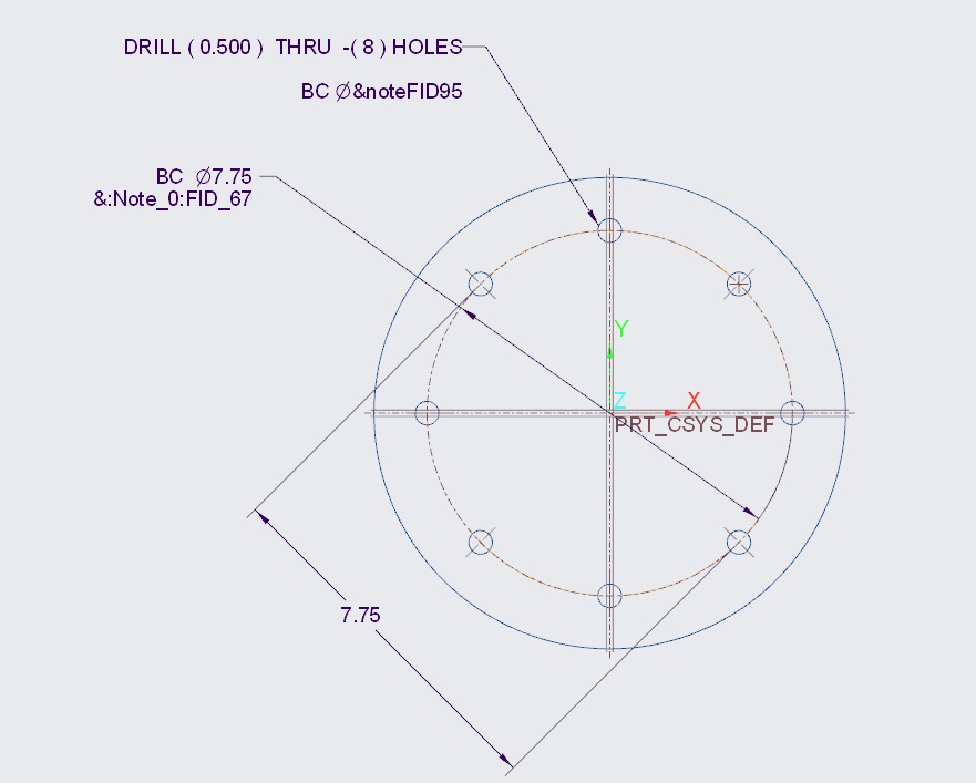
x6 ⌀.50↧THRU on ⌀8.0 BCD
Where the number of holes, the diameter and depth as well as the BC diameter and of course there would need to be the start position (12:00 or some angle off a reference etc...
Nov 13, 2025
11:25 PM
- Mark as New
- Bookmark
- Subscribe
- Mute
- Subscribe to RSS Feed
- Permalink
- Notify Moderator
Please log in to access translation
Nov 13, 2025
11:25 PM
If I understand correctly, you need a Bolt Circle Dia that appear in the drawing with dimensions automatically.
If yes, Follow the method detailed below.
Create a Revolved Feature Say a Flanged Part using a Datum Centerline. This would ensure that the Sketch Dimensions are a Diameter.

Create a Hole on the face and select Diameter from the Type Pull down Menu.
Select The Axis of the Flange and a Plane for Orientation


With the Hole selected, Create an Axis Pattern by selecting the central axis. of the Flanged part.


Create a Drawing and place the views
Show Model Annotations. Select all the dimensions, Notes and all the axes.


You have your drawing ready.

---
Regards
Srinivasan Iyer
Regards
Srinivasan Iyer
Sep 29, 2025
10:09 PM
- Mark as New
- Bookmark
- Subscribe
- Mute
- Subscribe to RSS Feed
- Permalink
- Notify Moderator
Please log in to access translation
Sep 29, 2025
10:09 PM
Ken,
Now that I have a "workaround " to the lack of direct application of reference circle and dimensioning it, I discover that I can't make a note that includes the hole details and the bolt circle info. I would think a hole note that sees the quantity of holes and the detail of the diameter would report the bolt circle diameter as well. It's a partial note. I tried all sorts of parameter note tricks to no avail.
In theory, If I make a hole using the hole tool, then array it in a circle using the pattern-axis tool, Creo should combine all that into a dimension or a note available in "show model annotations" dialog box. I tried switch dimensions to find the reference for the dim. I also tried the &feature ID method to call it up. Seems like this is not an odd request. bolt circles are a common thing in engineering.
Aug 27, 2025
12:16 AM
- Mark as New
- Bookmark
- Subscribe
- Mute
- Subscribe to RSS Feed
- Permalink
- Notify Moderator
Please log in to access translation
Aug 27, 2025
12:16 AM
You are in the wrong forum.
PTC has two CAD systems: Creo+ and Creo Parametric and Creo Elements Direct.
Which makes it confusing.
More, for Creo Elements Direct:
- The 3D software name is Modeling, and
- The 2D software name is Drafting.
For Creo+ and Creo Parametric, use only this tab:

You should move your post to this community to have a better chance to get an answer.
To move your post, click on the three vertical dots on your initial post and click on "Notify Moderator".
http://kotom.eng.free.fr
Aug 27, 2025
08:31 AM
- Mark as New
- Bookmark
- Subscribe
- Mute
- Subscribe to RSS Feed
- Permalink
- Notify Moderator
Please log in to access translation
Aug 27, 2025
08:31 AM
In order to show the dimensions you want, you need to define the model in the same way. I would suggest redefining the first hole from radial to diameter to show the diameter dimension.

Otherwise you need to add your own dimension. Selecting the bolt circle twice will create a diameter dimension. You can also change a created dimension by changing the "Orientation":

There is always more to learn in Creo.


