
Turn on suggestions
Auto-suggest helps you quickly narrow down your search results by suggesting possible matches as you type.
Showing results for
Please log in to access translation
Turn on suggestions
Auto-suggest helps you quickly narrow down your search results by suggesting possible matches as you type.
Showing results for
Community Tip - Visit the PTCooler (the community lounge) to get to know your fellow community members and check out some of Dale's Friday Humor posts! X
- Community
- Creo+ and Creo Parametric
- 3D Part & Assembly Design
- CREO 2.0: Creating surface/volume regions in subc...
Translate the entire conversation x
Please log in to access translation
Options
- Subscribe to RSS Feed
- Mark Topic as New
- Mark Topic as Read
- Float this Topic for Current User
- Bookmark
- Subscribe
- Mute
- Printer Friendly Page
CREO 2.0: Creating surface/volume regions in subcomponents of assembly
Mar 24, 2014
04:49 PM
- Mark as New
- Bookmark
- Subscribe
- Mute
- Subscribe to RSS Feed
- Permalink
- Notify Moderator
Please log in to access translation
Mar 24, 2014
04:49 PM
CREO 2.0: Creating surface/volume regions in subcomponents of assembly
Whenever I try to add a surface or a volume region to a subcomponent of an assembly, it fails. In order to add the surface/volume region, I must open that part by itself and add the surface/volume region there. However, the location of my surface region in one component is dependent on the position of other components within the assembly. This makes locating the surface/volume region very annoying. Does anyone else have this headache?
This thread is inactive and closed by the PTC Community Management Team. If you would like to provide a reply and re-open this thread, please notify the moderator and reference the thread. You may also use "Start a topic" button to ask a new question. Please be sure to include what version of the PTC product you are using so another community member knowledgeable about your version may be able to assist.
Labels:
- Labels:
-
Assembly Design
11 REPLIES 11
Mar 25, 2014
07:46 AM
- Mark as New
- Bookmark
- Subscribe
- Mute
- Subscribe to RSS Feed
- Permalink
- Notify Moderator
Please log in to access translation
Mar 25, 2014
07:46 AM
Jack,
Check your external reference settings. This may be preventing you from doing it in the assembly.
Hope this Helps,
Don Anderson
Mar 25, 2014
08:59 AM
- Mark as New
- Bookmark
- Subscribe
- Mute
- Subscribe to RSS Feed
- Permalink
- Notify Moderator
Please log in to access translation
Mar 25, 2014
08:59 AM
I don't have any restraints on external referencing in my settings, that I can see. Were you thinking of a specific option that might cause this problem?
Mar 25, 2014
09:19 AM
- Mark as New
- Bookmark
- Subscribe
- Mute
- Subscribe to RSS Feed
- Permalink
- Notify Moderator
Please log in to access translation
Mar 25, 2014
09:19 AM
Jack,
When you add a surface or volume region at the assembly level it will be stored in the part file but you should be able to define it at the assembly level.
Do any of the parts have features created with a module requiring a floating license?
See if your settings are are simalar to these below.
File > Options > Assesmbly >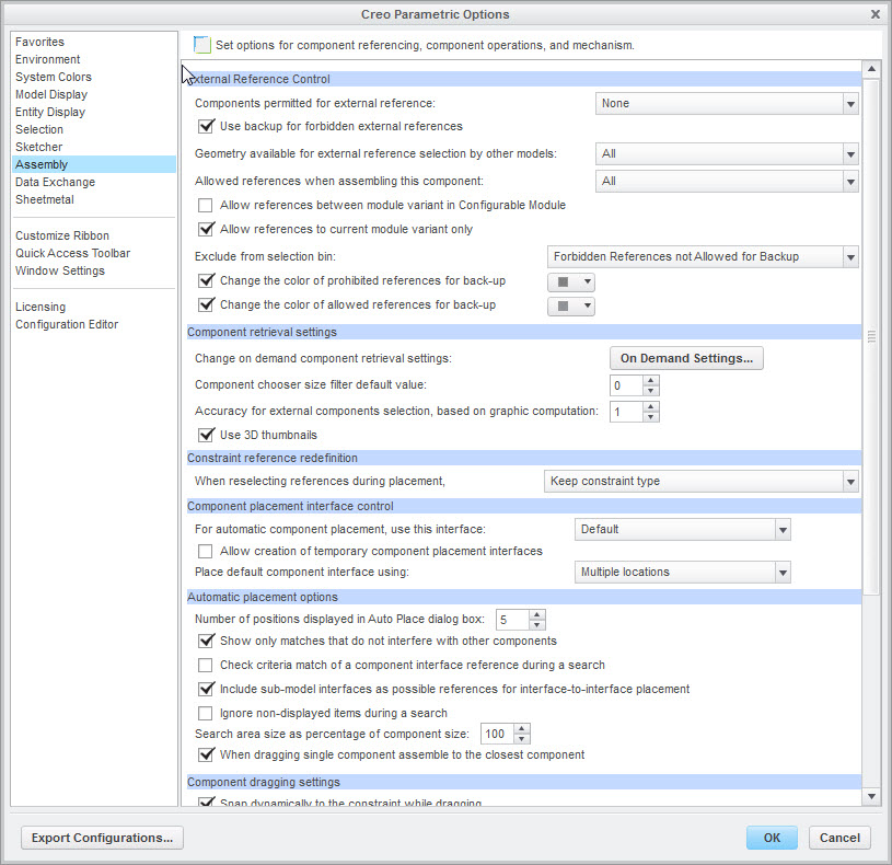
Don
Mar 25, 2014
09:44 AM
- Mark as New
- Bookmark
- Subscribe
- Mute
- Subscribe to RSS Feed
- Permalink
- Notify Moderator
Please log in to access translation
Mar 25, 2014
09:44 AM
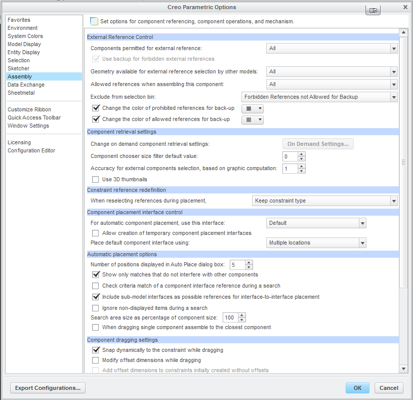
Our first option is set differently. It looks like if I set it up your way, any components I would change are backed up to the directory I'm working in, so as to not change the original file?
Mar 25, 2014
10:48 AM
- Mark as New
- Bookmark
- Subscribe
- Mute
- Subscribe to RSS Feed
- Permalink
- Notify Moderator
Please log in to access translation
Mar 25, 2014
10:48 AM
Jack,
That option should not create any additional files. It should only allow the reference to be copied into the model so the parent model won't be needed in session and allow you to uncheck Dependent in the options.
Once you have created your sketch for the surface/volume region I would delete any reference other components/subassemblies so no external reference exist.
Hope this helps,
Don Anderson
Mar 25, 2014
02:04 PM
- Mark as New
- Bookmark
- Subscribe
- Mute
- Subscribe to RSS Feed
- Permalink
- Notify Moderator
Please log in to access translation
Mar 25, 2014
02:04 PM
Using this option doesn't seem to change anything. I need to add the region at the component level still. I think it's a Windchill issue.
Nov 14, 2014
12:12 PM
- Mark as New
- Bookmark
- Subscribe
- Mute
- Subscribe to RSS Feed
- Permalink
- Notify Moderator
Please log in to access translation
Nov 14, 2014
12:12 PM
Hi All,
Im running into a similar issue. I have three parts (all Sheet metal). I can assign a surface region on one part, but the other two give me a "Geometrical Reference Error" and cannot proceed. I can add teh region to the parts individually, but not in the assembly.
Any ideas?
Nov 14, 2014
01:43 PM
- Mark as New
- Bookmark
- Subscribe
- Mute
- Subscribe to RSS Feed
- Permalink
- Notify Moderator
Please log in to access translation
Nov 14, 2014
01:43 PM
Paul,
Surface regions are stored in the part files, not in the assembly file. To avoid external references it's better to create the surface or volume regions in the part files.
Don
Nov 14, 2014
03:14 PM
- Mark as New
- Bookmark
- Subscribe
- Mute
- Subscribe to RSS Feed
- Permalink
- Notify Moderator
Please log in to access translation
Nov 14, 2014
03:14 PM
Hi Don,
Then why can I add it to one part, but not the other two? I'll assume it has somethign to do with adding eh reagion to eh first part, the grounded part, the 'default' constrained part.
Nov 14, 2014
04:22 PM
- Mark as New
- Bookmark
- Subscribe
- Mute
- Subscribe to RSS Feed
- Permalink
- Notify Moderator
Please log in to access translation
Nov 14, 2014
04:22 PM
Paul,
Is it the same part that you are trying to perform the function too?
Are the parts mirrored?
There may be an external reference that is only available at the assembly level that is interfering with the creation of the surface region.
My guess is that there is a feature/reference at the assembly level that is interfering.
Don
Feb 15, 2016
03:15 PM
- Mark as New
- Bookmark
- Subscribe
- Mute
- Subscribe to RSS Feed
- Permalink
- Notify Moderator
Please log in to access translation
Feb 15, 2016
03:15 PM
You can't create a surface or volume region at the assembly level if there is an assembly-level cut - BUT, you can use "Solidify" to make an assembly-level-like cut in your model (my need for this is typically for symmetry use) ... then you can make a surface or volume region in Simulate. Of course, there will be cases where you cannot use this approach if the model requires assembly-level cuts to represent your real process.
Chris


