
Turn on suggestions
Auto-suggest helps you quickly narrow down your search results by suggesting possible matches as you type.
Showing results for
Please log in to access translation
Turn on suggestions
Auto-suggest helps you quickly narrow down your search results by suggesting possible matches as you type.
Showing results for
Community Tip - Have a PTC product question you need answered fast? Chances are someone has asked it before. Learn about the community search. X
- Community
- Creo+ and Creo Parametric
- 3D Part & Assembly Design
- Re: Can I assemble a jpeg or other image file into...
Translate the entire conversation x
Please log in to access translation
Options
- Subscribe to RSS Feed
- Mark Topic as New
- Mark Topic as Read
- Float this Topic for Current User
- Bookmark
- Subscribe
- Mute
- Printer Friendly Page
Can I assemble a jpeg or other image file into an assembly with Creo 2?
Oct 16, 2014
09:30 AM
- Mark as New
- Bookmark
- Subscribe
- Mute
- Subscribe to RSS Feed
- Permalink
- Notify Moderator
Please log in to access translation
Oct 16, 2014
09:30 AM
Can I assemble a jpeg or other image file into an assembly with Creo 2?
I currently develop and design educational furniture. Some table assemblies now have images printed on them. How can I introduce these images onto the tabletops in the assembly stage using Creo 2 as my preferred design tool?
This thread is inactive and closed by the PTC Community Management Team. If you would like to provide a reply and re-open this thread, please notify the moderator and reference the thread. You may also use "Start a topic" button to ask a new question. Please be sure to include what version of the PTC product you are using so another community member knowledgeable about your version may be able to assist.
Solved! Go to Solution.
Labels:
- Labels:
-
Surfacing
ACCEPTED SOLUTION
Accepted Solutions
Nov 07, 2014
11:46 AM
- Mark as New
- Bookmark
- Subscribe
- Mute
- Subscribe to RSS Feed
- Permalink
- Notify Moderator
Please log in to access translation
Nov 07, 2014
11:46 AM
That is a good solution to keep from duplicating the desktop surface.
I don't know why the image editor would not open the BMP file. It is not unusual to have to know photoshop (or like app) to get what you want in Creo.
Feel free to mark your answer as correct. I think it is a good solution.
7 REPLIES 7
Oct 16, 2014
09:43 AM
- Mark as New
- Bookmark
- Subscribe
- Mute
- Subscribe to RSS Feed
- Permalink
- Notify Moderator
Please log in to access translation
Oct 16, 2014
09:43 AM
I do this with labels and silk screens. The jpeg cannot be added to an assembly directly, but you can create a part that acts like a silkscreen. Use bmp, or tiff files if you want a good quality image or have transparent portions. Jpeg compresses the file, so the colors are off.
Steps for making an image in Creo:
1. Add the Creo config option save_texture_with_model=yes to your config.pro
2. Created a bmp file of the image with all transparent portions need to be the same color. Default is white.
3. Open the image in the Creo image editor (tools/image editor). Create an alpha channel, using the color from step 2. White is the default, so you can just select ok.
4. Save this file as a decal or .tx4 file.
5. Create a thin model that will be your silkscreen part. Go to the appearances manager. Create new color that is 100% transparent and add the decal file to the 2nd tab in the color editor.
6. Add this color to the a part by selecting on the model tree.
7. Go to the Model Appearance editor and use the eye drop tool (upper right) and select the part.
8. Change the mapping type to planar. Adjust the size, angle and number of patterns (typically single) for the color.
9. Enjoy!
Oct 16, 2014
10:05 AM
- Mark as New
- Bookmark
- Subscribe
- Mute
- Subscribe to RSS Feed
- Permalink
- Notify Moderator
Please log in to access translation
Oct 16, 2014
10:05 AM
Thanks Michael,
Sounds complicated but I'll have a go!
Oct 16, 2014
02:20 PM
- Mark as New
- Bookmark
- Subscribe
- Mute
- Subscribe to RSS Feed
- Permalink
- Notify Moderator
Please log in to access translation
Oct 16, 2014
02:20 PM
Thought I'd give this a try as well. Here are some steps (while obvious to some, were not to me as I'm still kind of new to CREO 2.0).
2.5) Open a part in CREO 2.0, then go to the Tools tab, then over to the right to Image Editor.
3.5) To create alpha channel, in the Image Editor, go to Image, Create Alpha Channel. For white, R, G, and B should all be 255. Go to View, Display Alpha Channel. Everything in black will be transparent.
After step 5 I wasn't able to follow the directions to get the results. I did however figure out another way to do it.
1) Have a part modeled like described (I just went to extrude, drew a line, green check mark to okay, prompted me saying it was going to be a surface, chose extrude length, and press green check mark again...resulting in surface).
2) Go to the View tab, then under the icons of Appearance Gallery, Section Manage Views, and Display Style, you will see the words Model Display. Click on Model Display for the drop-down and click on Images
3) Click on the Add icon and find the file you created from step 4 in Michael's post. Adjust as you see fit and press OK.
Oct 16, 2014
03:38 PM
- Mark as New
- Bookmark
- Subscribe
- Mute
- Subscribe to RSS Feed
- Permalink
- Notify Moderator
Please log in to access translation
Oct 16, 2014
03:38 PM
You do need to do this at the part level for best control, but a decal with transparency can work at assembly levels if the rest of the part can be one appearance.
Know that you can add a decal over an appearance as well. You can have a wood grain with texture, and on that you can add a decal. Just be careful with textures as they have to match the mapping of the appearance. PhotoRender or PhotoLux will bring out the depth to make the texture work for you. In Creo 2.0, texture gets kind of mucky as it is a haze over the appearance.
The internal editor will generate the .tx(n) files. If you have a clearly segregated alpha color, it does a nice job of making transparencies. I use bitmap .BMP files as masters to start exclusively as they seem to be the most robust when working in Creo.
There is no easy way to have the same assembly multiples at a higher level of assembly have different appearances applied. It is a serious shortcoming in Creo. For most practical purposes, each requires its own unique configuration. The easiest thing I can come up with is making the surface you want to vary in multiples at the part level, each with its own unique decal/appearance. In family tables or display states, you can manage which version you see. In your assembly, you can easily replace the element. And I am not sure just how many roadblocks or bugs you run into trying to make this work. I'll have to give this some thought and attempts to know know for sure.
Nov 07, 2014
06:18 AM
- Mark as New
- Bookmark
- Subscribe
- Mute
- Subscribe to RSS Feed
- Permalink
- Notify Moderator
Please log in to access translation
Nov 07, 2014
06:18 AM
Ok, I have tried the .bmp file but it will not open for some reason so therefore I cannot change it to a tx4 file.
However, I have tried another method that has success, albeit you have to have some knowledge of photoshop.
Image manipulation:
1. Open the selected image in photoshop as a jpeg file and make 200-400 pixels/inch or similar
2. Resized it to fit into the area created by the part.
3. Add rounded corners to suit surface area as required.
Image insertion:
1. Open part and add new datum plane or surface to float 0.1 mm above solid surface (if you don't do this then the image can merge with the solid surface)
2. In view tab, click on model display and then images then add.
3. Click on new datum plane or surface and the image will lay on that surface.
4. Move and manipulate the image to fit into the aperture or area as made in the part.
5. Click okay.
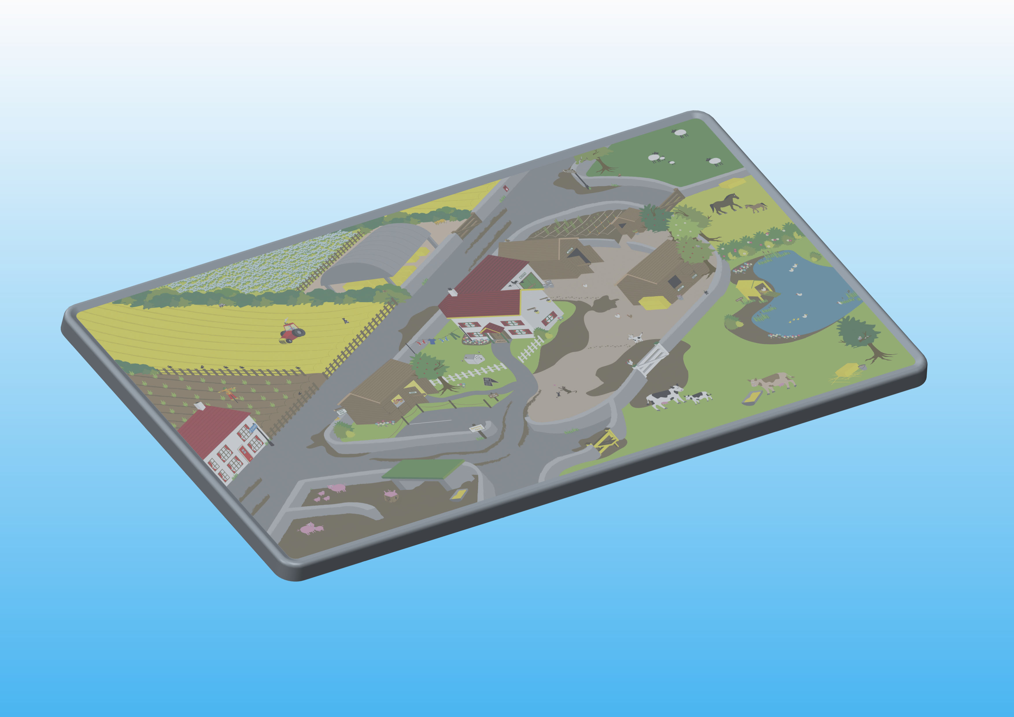
Now I know this is not the best of image quality but it is fairly simple to do and it will be reflected in any assembly you subsequently have.
Image below on part:
Nov 07, 2014
11:46 AM
- Mark as New
- Bookmark
- Subscribe
- Mute
- Subscribe to RSS Feed
- Permalink
- Notify Moderator
Please log in to access translation
Nov 07, 2014
11:46 AM
That is a good solution to keep from duplicating the desktop surface.
I don't know why the image editor would not open the BMP file. It is not unusual to have to know photoshop (or like app) to get what you want in Creo.
Feel free to mark your answer as correct. I think it is a good solution.
Jun 29, 2015
04:48 PM
- Mark as New
- Bookmark
- Subscribe
- Mute
- Subscribe to RSS Feed
- Permalink
- Notify Moderator
Please log in to access translation
Jun 29, 2015
04:48 PM
Just as an addendum to the comments above: I have subsequently tried to assemble more images and have come up against a problem.The images were created in Illustrator and then had a mask added to create rounded corners. When I tried to assemble the image into the CAD assembly all I got was a grey layer. The image was a high res Photoshop Jpeg. These can preserve metadata such as masks. My thought is that this might conflict with CAD and then may be then corrupting to show a grey box only.
The answer is to save the file as a web friendly jpeg and this should work.Don't forget to make sure the transparency is set to 0% to get the most from your image.


