
Turn on suggestions
Auto-suggest helps you quickly narrow down your search results by suggesting possible matches as you type.
Showing results for
Please log in to access translation
Turn on suggestions
Auto-suggest helps you quickly narrow down your search results by suggesting possible matches as you type.
Showing results for
Community Tip - Learn all about PTC Community Badges. Engage with PTC and see how many you can earn! X
- Community
- Creo+ and Creo Parametric
- 3D Part & Assembly Design
- Re: Can't extrude sketch as solid, only as surface
Translate the entire conversation x
Please log in to access translation
Options
- Subscribe to RSS Feed
- Mark Topic as New
- Mark Topic as Read
- Float this Topic for Current User
- Bookmark
- Subscribe
- Mute
- Printer Friendly Page
Can't extrude sketch as solid, only as surface
Oct 09, 2015
08:17 PM
- Mark as New
- Bookmark
- Subscribe
- Mute
- Subscribe to RSS Feed
- Permalink
- Notify Moderator
Please log in to access translation
Oct 09, 2015
08:17 PM
Can't extrude sketch as solid, only as surface
Hi,
I'm working in an assembly, created new component as solid, and in that if I make a random sketch, and try to extrude it, it will only allow me to extrude it as surface, and i can't click on "extrude as solid" button. No matter how simple the sketch is.
What's causing this and how could i get it working?
Thanks in advance:)
This thread is inactive and closed by the PTC Community Management Team. If you would like to provide a reply and re-open this thread, please notify the moderator and reference the thread. You may also use "Start a topic" button to ask a new question. Please be sure to include what version of the PTC product you are using so another community member knowledgeable about your version may be able to assist.
Solved! Go to Solution.
Labels:
- Labels:
-
Assembly Design
ACCEPTED SOLUTION
Accepted Solutions
Oct 09, 2015
08:45 PM
- Mark as New
- Bookmark
- Subscribe
- Mute
- Subscribe to RSS Feed
- Permalink
- Notify Moderator
Please log in to access translation
Oct 09, 2015
08:45 PM
Papp,
I believe that you cannot create solid geometry while you are working on an assembly. This is because at assembly you can only remove material, not create it. You can do it as a surface because it can be use for references for new components assembled, space claims for skeletons, etc...
Remember, you cannot create material at assembly level.
11 REPLIES 11
Oct 09, 2015
08:45 PM
- Mark as New
- Bookmark
- Subscribe
- Mute
- Subscribe to RSS Feed
- Permalink
- Notify Moderator
Please log in to access translation
Oct 09, 2015
08:45 PM
Papp,
I believe that you cannot create solid geometry while you are working on an assembly. This is because at assembly you can only remove material, not create it. You can do it as a surface because it can be use for references for new components assembled, space claims for skeletons, etc...
Remember, you cannot create material at assembly level.
Oct 10, 2015
05:48 AM
- Mark as New
- Bookmark
- Subscribe
- Mute
- Subscribe to RSS Feed
- Permalink
- Notify Moderator
Please log in to access translation
Oct 10, 2015
05:48 AM
Thanks for the info
I was following a tutorial on modeling a car jack.
I think i did exactly like there :
1. Create a .prt where I make a simple sketch for every carjack part with the correct base dimensions, lenght etc.
2. Create assembly, add this sketch to it
3. Create new components for every part in assembly mode using the lines from that sketch
In there somehow he managed to extrude as solid.
So my question : Now that I have created that sketch, how should I create parts in the assembly using those lines as lenght, dimensions reference?
-For every part I should make a new sketch first, project the lines from the "helping sketch" to get those dimensions, than open the part's .prt separately, and there I should edit it, extrude as solid?
How would you do it? Please write step-by-step how should I open the part's .prt separately
Tutorial's pictures:
Here's how mine looks : ( mine is surface extrude, hollow through)
Thanks! (sorry for the english)
Oct 10, 2015
08:53 AM
- Mark as New
- Bookmark
- Subscribe
- Mute
- Subscribe to RSS Feed
- Permalink
- Notify Moderator
Please log in to access translation
Oct 10, 2015
08:53 AM
Edit : Well i figured out a way, no need for more help:)
(I just copyed the whole "helping" sketch, made new part from it, than added itt to the assembly, where there's the original sketch so i can assure the part's good placement. so I copy that sketch for every new part
Thanks again
Oct 10, 2015
03:06 PM
- Mark as New
- Bookmark
- Subscribe
- Mute
- Subscribe to RSS Feed
- Permalink
- Notify Moderator
Please log in to access translation
Oct 10, 2015
03:06 PM
Papp,
Nice to know that you figured out! I must confess that I didn't find the solution for that. However, this procedure may help in order to work better (or maybe not).
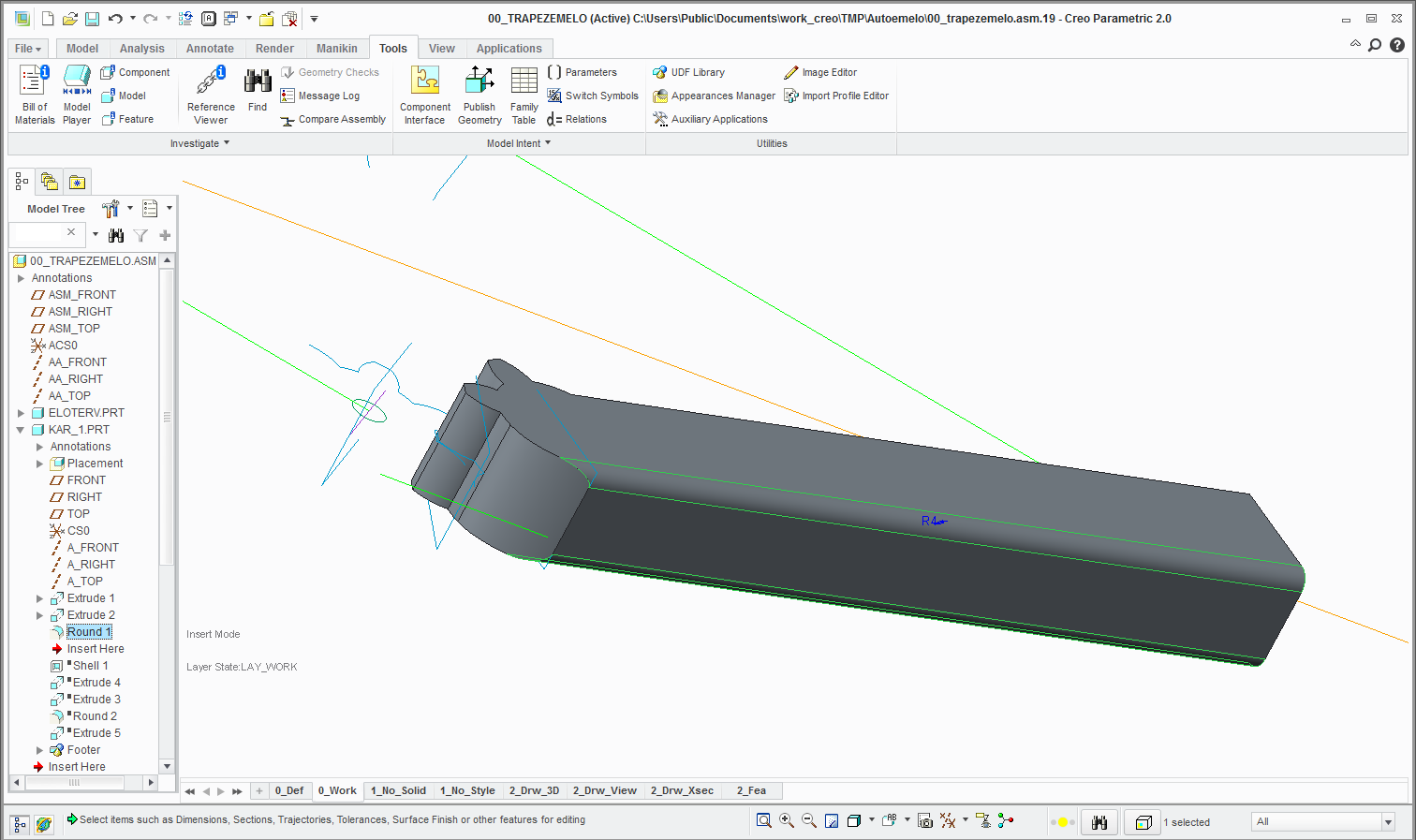
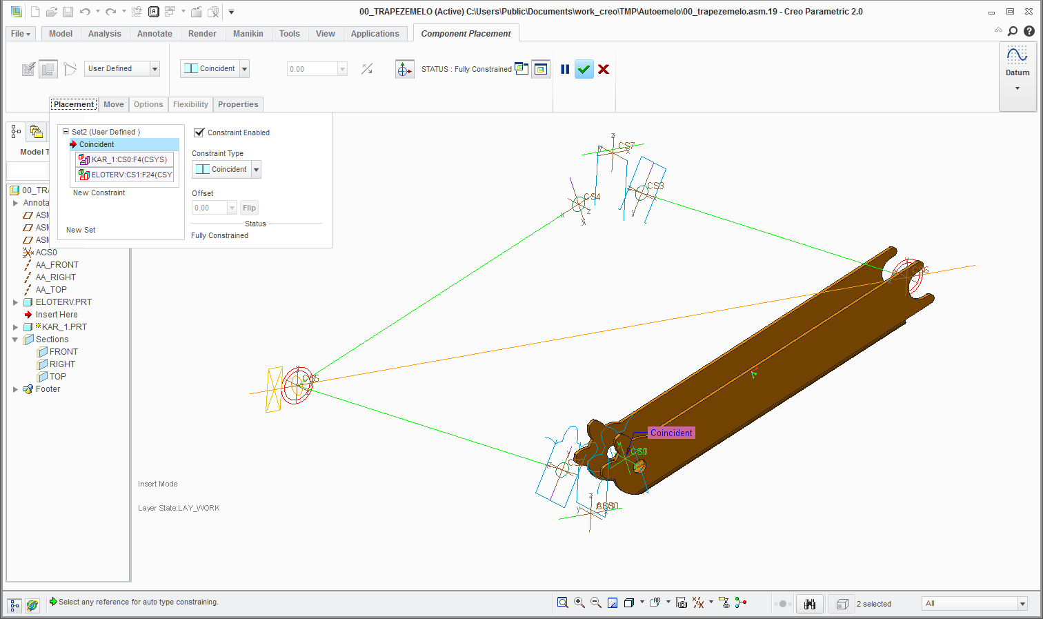
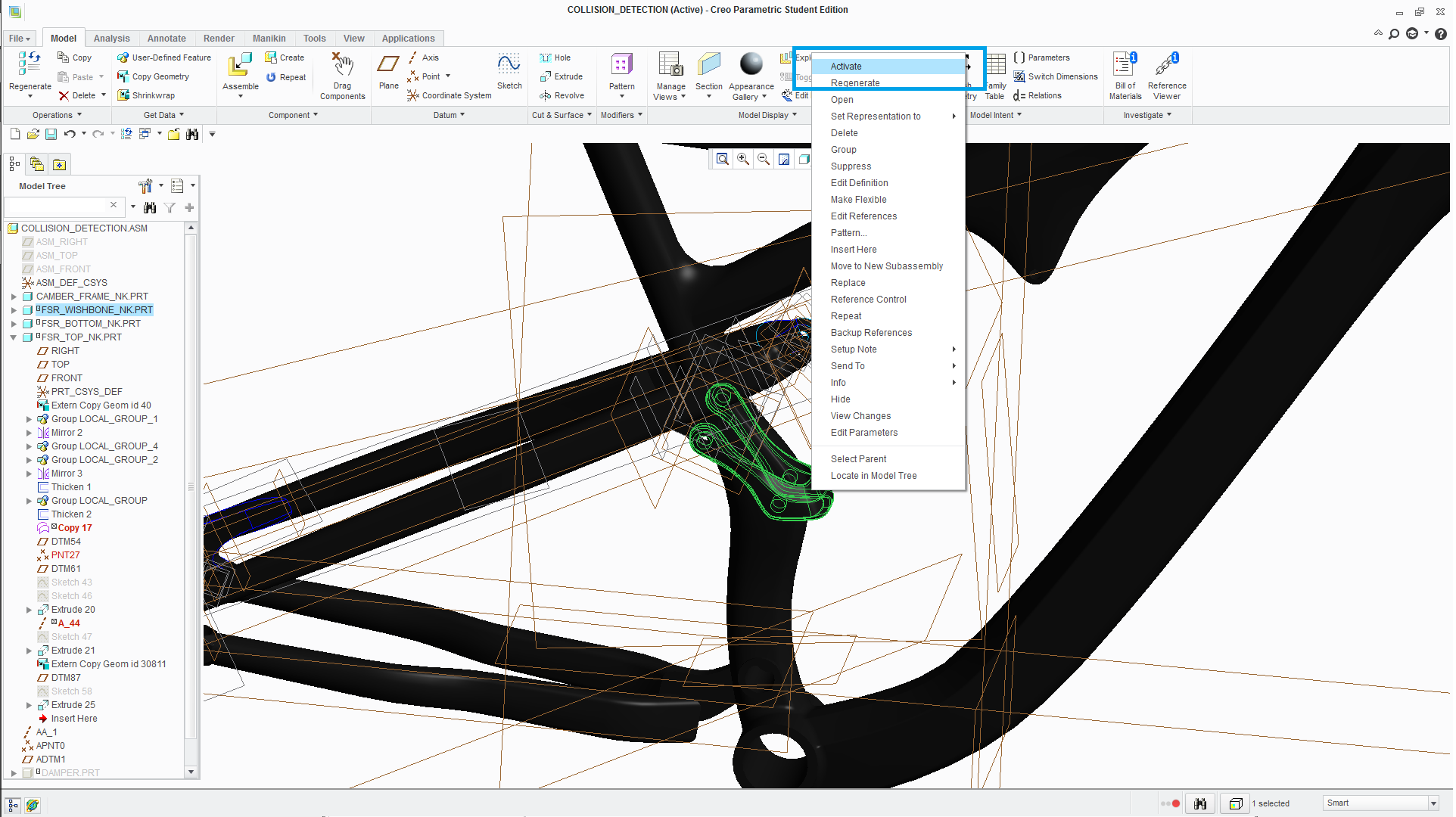
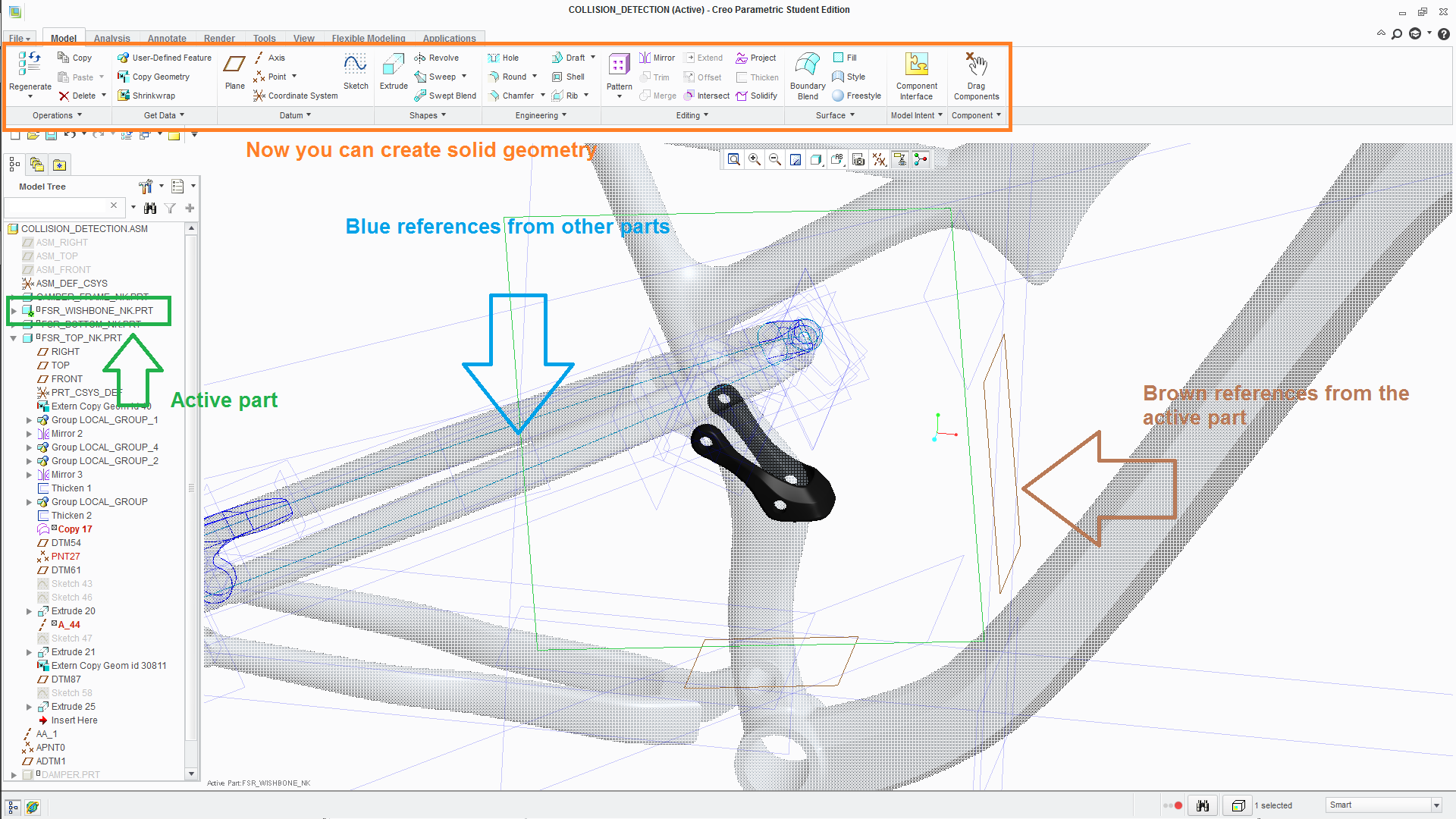
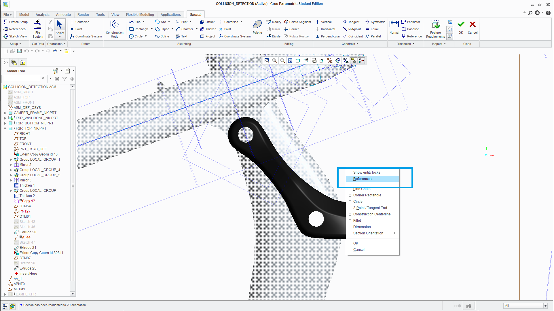
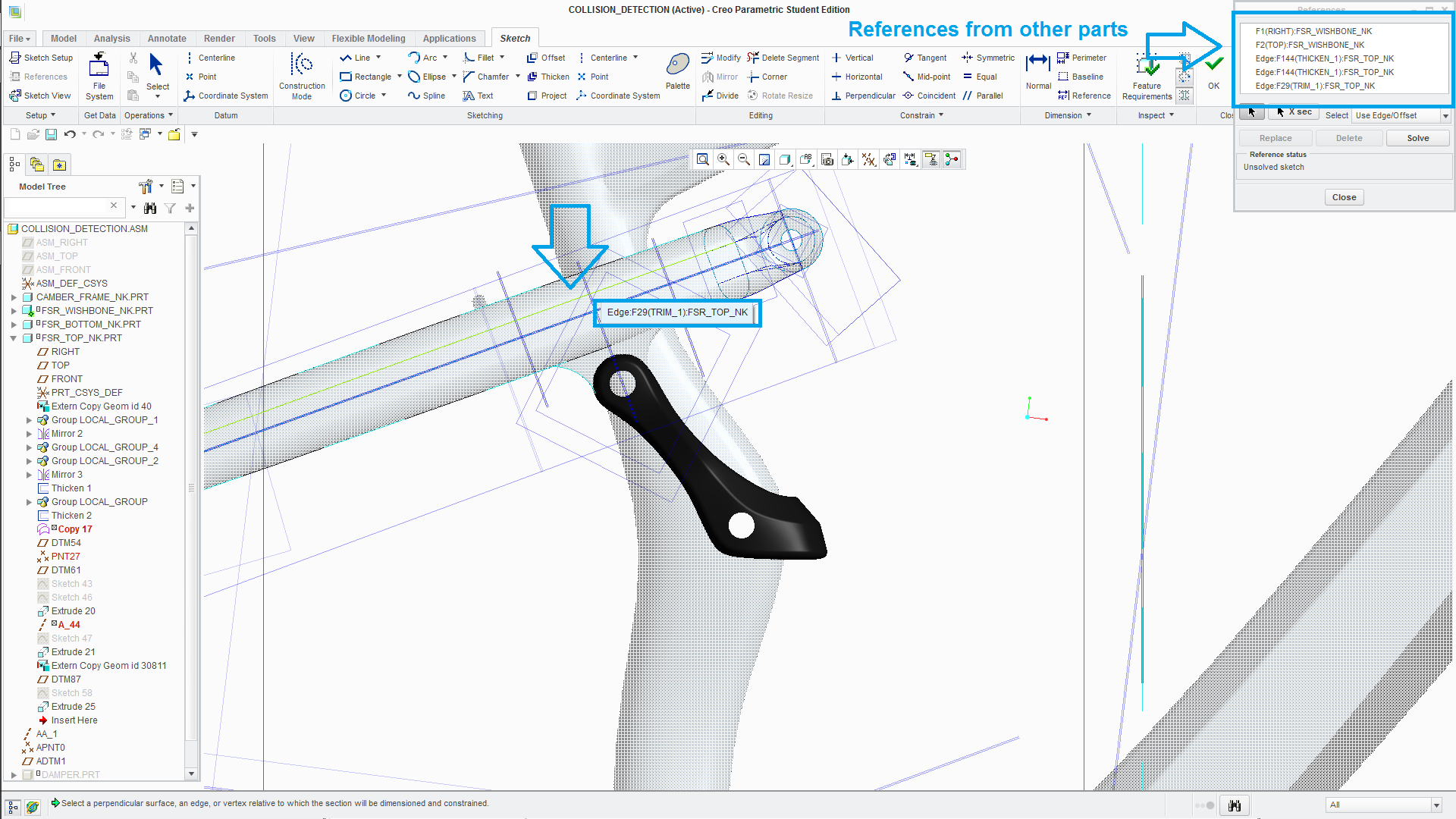
- Remember that you can right-click any part at assembly level an by clicking Activate, you are now able to create solid geometry (solid extrude in your case), only for that specific part. (picture 1 and 2)
- Remember also, that when the part is active, you will see all the references from each part. And you can use them! (Some blues other browns). (picture 2)
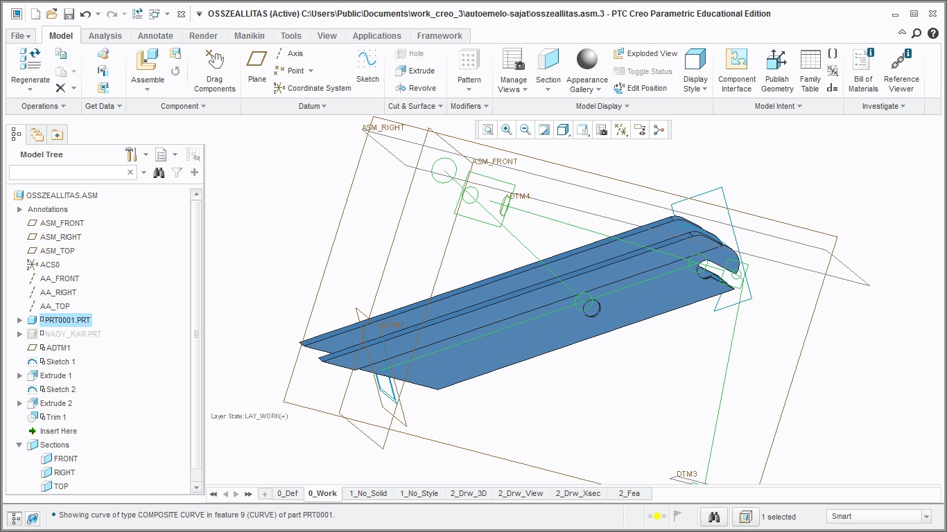
- Finally, the important thing is here. You can Sketch at a part level, and while sketching, you can select any kind of references from the other parts of your assembly (from the assembly and from the parts of the assembly). (picture 3 and 4)
- So, in a few words. You are able to select any kind of references from the other parts (already assembled) and you are able to create solid geometry using that references (planes for example, that could define the length of an extrude). The only thing that you have to do, is Activate the part and it will be like working in an ordinary .prt file, the advantage is that you have the "assembly" references. (picture 3 and 4)
Nice weekend!
Oct 11, 2015
04:38 PM
- Mark as New
- Bookmark
- Subscribe
- Mute
- Subscribe to RSS Feed
- Permalink
- Notify Moderator
Please log in to access translation
Oct 11, 2015
04:38 PM
wow, thanks, you're really helpful, i'll use these tricks.
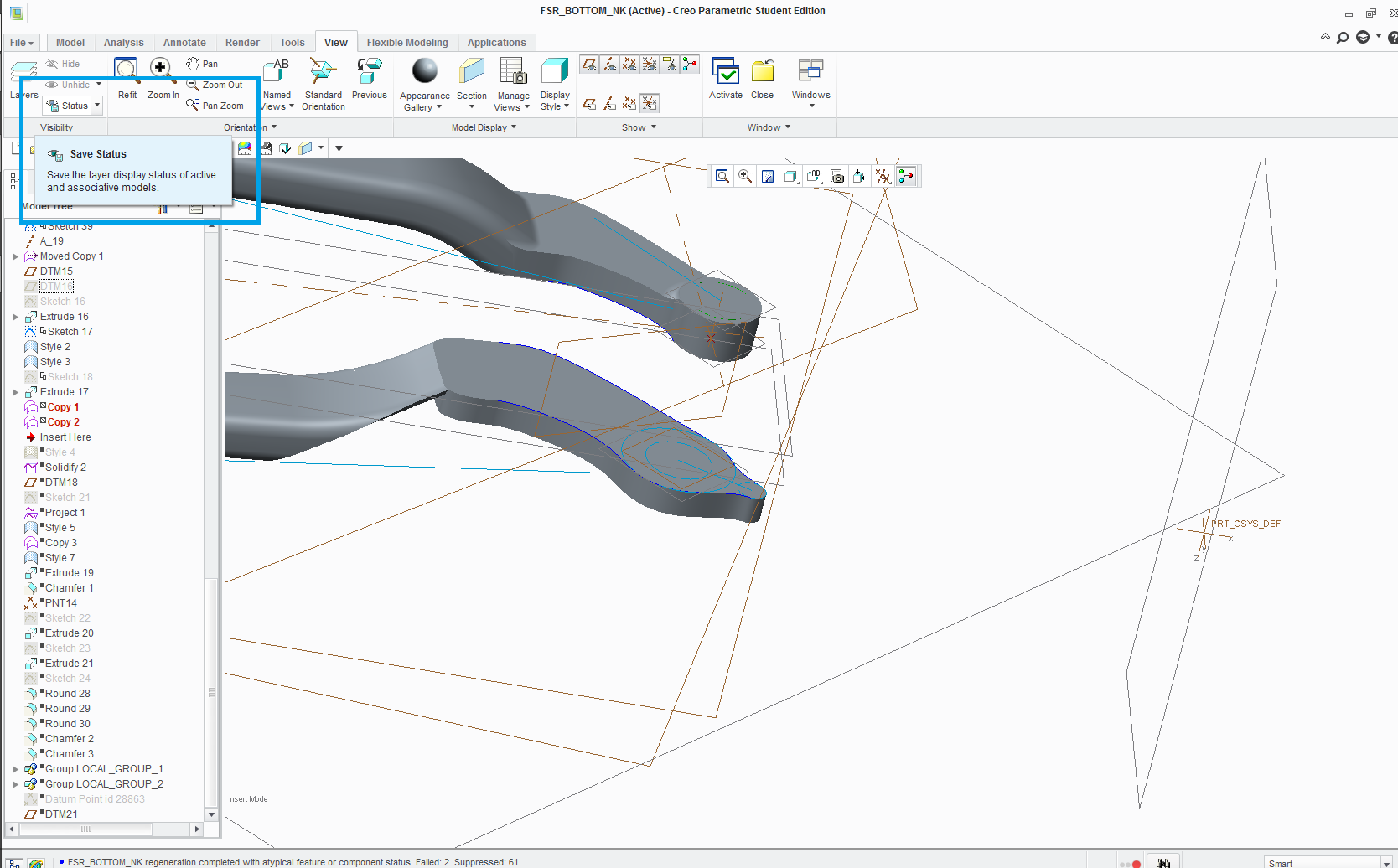
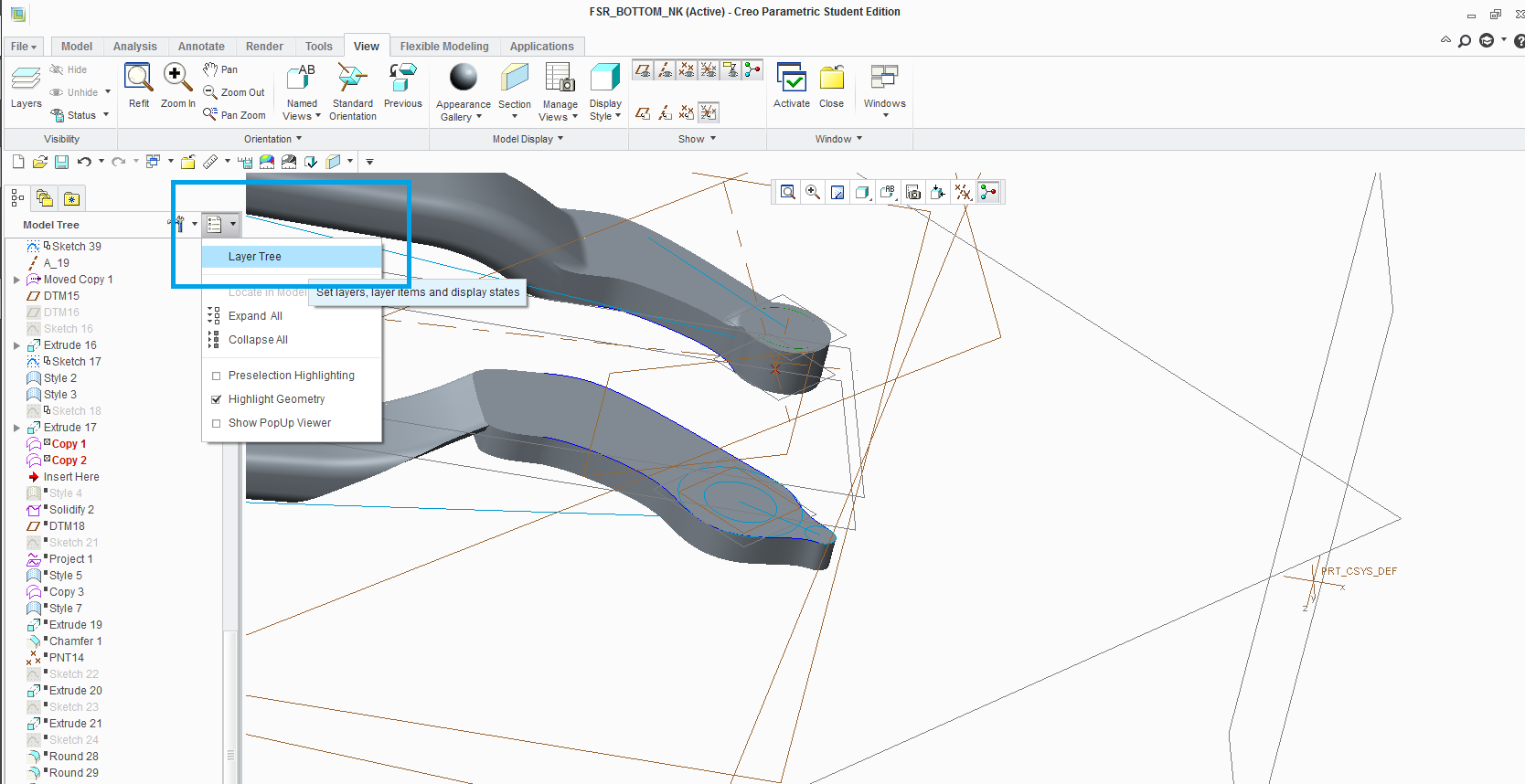
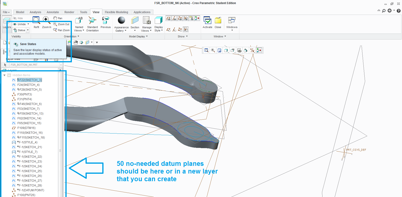
Though I can never handle all these datum planes without them annoying me.
When i select all like 50 non-needed datumplanes, and hide them, and save the assembly, when I exit and reopen it, all of them will be visible again:P
Same with sketches, can't hide them properly.
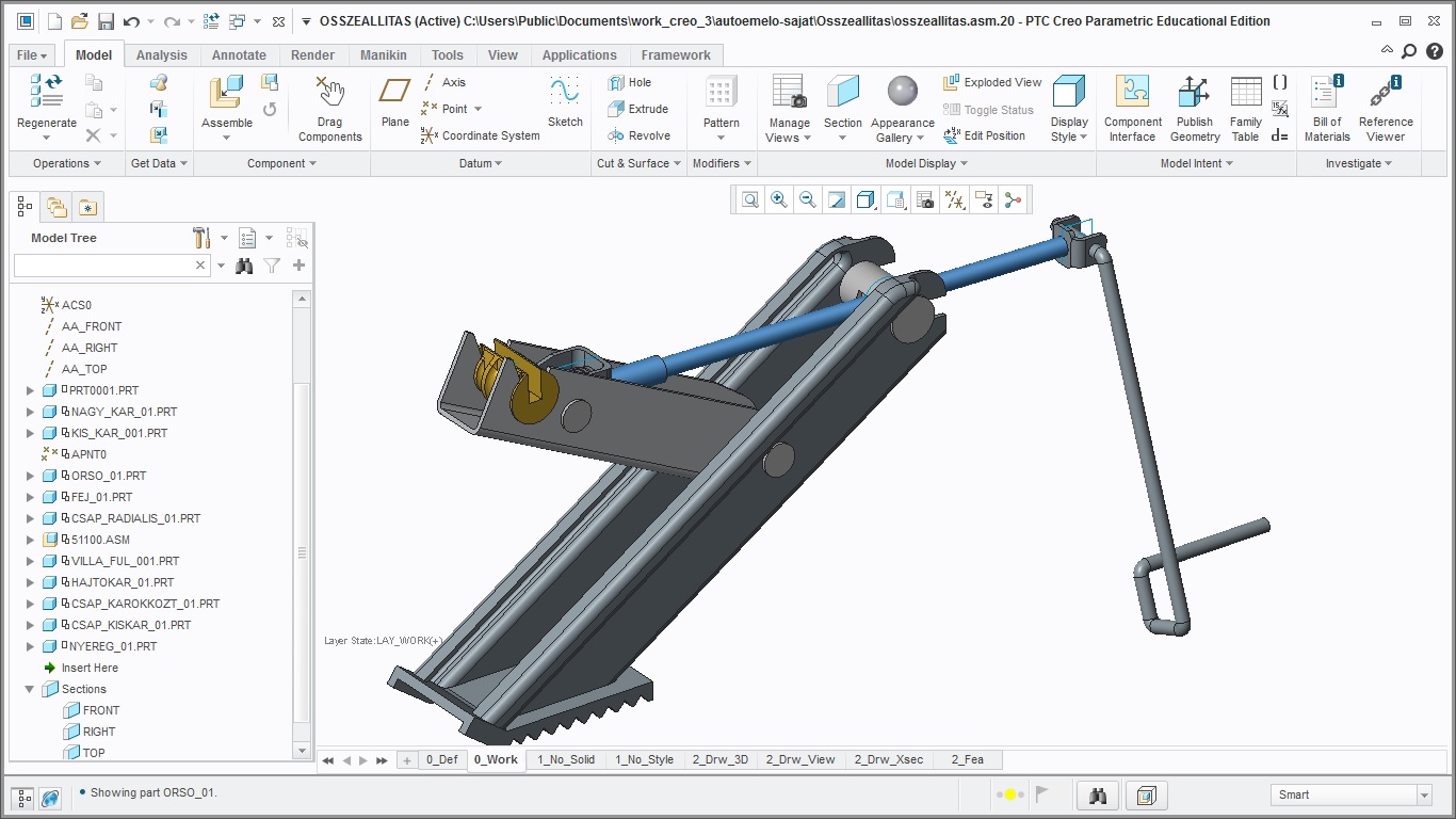
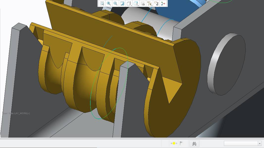
Btw here's the result, some random primitive homework for university:)
Oct 11, 2015
11:26 PM
- Mark as New
- Bookmark
- Subscribe
- Mute
- Subscribe to RSS Feed
- Permalink
- Notify Moderator
Please log in to access translation
Oct 11, 2015
11:26 PM
That happens when you do not save the layer display status.
Hidden items like planes, points, curves, even solid and surfaces are added to a layer named "Hidden" in the Layer Tree when you hide them from the graphics window or from the Model Tree. What happens is that Creo doesn't save that status unless you click in the Save Status button locate it in the view tab.
In a few words, before you exit:
- Save the model or assembly
- Save the layer display status
If you reopen that part or assembly, it should appear just like you want (without the 50 no-needed datum planes).
Check also this video for more info. Use your mail and password from this community if you need to.
Tutorial: Creating Layer States
Such a nice university and such a nice homework! You are lucky! Nice model that you have there.
Oct 20, 2015
06:27 PM
- Mark as New
- Bookmark
- Subscribe
- Mute
- Subscribe to RSS Feed
- Permalink
- Notify Moderator
Please log in to access translation
Oct 20, 2015
06:27 PM
Got overwhelmed by university duties , so i can only reply now..
You helped me so nicely i had remorse until i couldn't thank you
Also, the ptc tutorials was a good tip, i couldn't have found these on youtube
Its not that nice university though, (Hungary, BME), lot of unnecessary thing we have to learn..
Btw in the subject "machine parts 1", this car jack analysis+design+assembly drawing has been the same homework in the last 40 years for everyone, even my father did this when he was a student
Is that bike some university related project of yours? I see you use student edition creo : )
Oct 21, 2015
03:09 PM
- Mark as New
- Bookmark
- Subscribe
- Mute
- Subscribe to RSS Feed
- Permalink
- Notify Moderator
Please log in to access translation
Oct 21, 2015
03:09 PM
Well, at least yours show you the software, I guess. Mine is located in Venezuela, Universidad de Los Andes. And I totally understand the situation, in my university the lab of mechanical design is full of PENTIUM II PC's. Even open the cracked AutoCad 2010 in those things takes about 15 min. Poor computers.
Nice that you like the bike, it is not a university project. It is more likely my project, it is based on a Camber Pro Evo 2012 Specialized Bike. Learn Creo stuff by your own, is my recommendation for you, it works and it worth it. No matter the University, because my friend, as you can see you are not alone in that 
I use the student edition, yes. It is because buy the software has became a huge problem for me. However, it works perfectly at the modeling and assembly level. Simulations and manufacturing things are the critical things that this version doesn't have. But is a quite nice first step!
Oct 21, 2015
10:56 AM
- Mark as New
- Bookmark
- Subscribe
- Mute
- Subscribe to RSS Feed
- Permalink
- Notify Moderator
Please log in to access translation
Oct 21, 2015
10:56 AM
Be VERY careful making things at the assembly level. Yes, you can use quilts created at the assembly level and copy those at a part level and solidify them. BUT, if you use other PART references you've now created circular references that can cause HUGE problems. In a case like that, best to create a skeleton part and control everything from there via quilts, etc. and that will be the first part in your assemble. Or it can actually be done at the assembly level without a skeleton. But, parts should never be based on other parts for geometry (it's ok for assembly constraints), all references should be to assy or skeleton geometry.
Oct 21, 2015
12:41 PM
- Mark as New
- Bookmark
- Subscribe
- Mute
- Subscribe to RSS Feed
- Permalink
- Notify Moderator
Please log in to access translation
Oct 21, 2015
12:41 PM
Just a question for you Frank, as i'm good working with part, less with assemblies.
But, about circular references, if a have an assembly with 2 parts and second part features are driven from first part (some references of second part are in first part), does this situation creates circular references? I think not. If first part has no references on second part, it's impossible to have circular references. Am i wrong?
Thank for reply.
Oct 21, 2015
01:04 PM
- Mark as New
- Bookmark
- Subscribe
- Mute
- Subscribe to RSS Feed
- Permalink
- Notify Moderator
Please log in to access translation
Oct 21, 2015
01:04 PM
Most likely not a circular reference per se, but it would be easy to make one AFTER that. In practice, it is NEVER good to use other parts as references. If you're going to do a top-down design, do it the right way, and then there can be no chance.


