Community Tip - When posting, your subject should be specific and summarize your question. Here are some additional tips on asking a great question. X
- Community
- Creo+ and Creo Parametric
- 3D Part & Assembly Design
- Challenge Modeling Complex Curved Sheet Metal Flan...
- Subscribe to RSS Feed
- Mark Topic as New
- Mark Topic as Read
- Float this Topic for Current User
- Bookmark
- Subscribe
- Mute
- Printer Friendly Page
Challenge Modeling Complex Curved Sheet Metal Flange
- Mark as New
- Bookmark
- Subscribe
- Mute
- Subscribe to RSS Feed
- Permalink
- Notify Moderator
Challenge Modeling Complex Curved Sheet Metal Flange
Hi everyone,
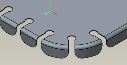
I'm trying to model a sheet metal part with a complex flange around its perimeter. The perimeter is curved and there are a lot of relief cuts in the part. The picture shows the part and the tool that is is formed on. I already have the flat pattern geometry including the flange. I've tried the 'Bend' command, but it will not work on curves--only straight lines. I've also tried making a die form (basically the inverse of the real tool with a recess in a block of material. I can't get this to work either--I think it is because it is bending around the perimeter that it won't work, but I'm not totally sure. The only other thing I can think of is trying to use the 'Flange' tool around a continuous perimeter, then unbend, then add the relief cutouts, and then rebend. This will be a lot more work, though--especially when I've got about 25 of these parts. Does anybody have an suggested approaches?
Thank you!
This thread is inactive and closed by the PTC Community Management Team. If you would like to provide a reply and re-open this thread, please notify the moderator and reference the thread. You may also use "Start a topic" button to ask a new question. Please be sure to include what version of the PTC product you are using so another community member knowledgeable about your version may be able to assist.
Solved! Go to Solution.
- Labels:
-
General
Accepted Solutions
- Mark as New
- Bookmark
- Subscribe
- Mute
- Subscribe to RSS Feed
- Permalink
- Notify Moderator
Hey Aero,
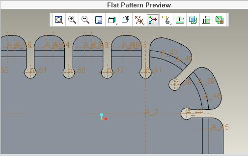
I have been playing around with this for a little while trying various techniques, and found that the best is to create your base planar surface, then create your flange, then us extrude to cut in the features I guess your calling the reliefs. It takes some doing but it is the only way I have found that will still give you your flat pattern shown below.


Hope it helps!
Buddy Hudson
- Mark as New
- Bookmark
- Subscribe
- Mute
- Subscribe to RSS Feed
- Permalink
- Notify Moderator
Sorry but your final observation it the right way. Unbend and bend back is a very nice tool to have. Imagine not having that ![]()
- Mark as New
- Bookmark
- Subscribe
- Mute
- Subscribe to RSS Feed
- Permalink
- Notify Moderator
Hey Aero,
I have been playing around with this for a little while trying various techniques, and found that the best is to create your base planar surface, then create your flange, then us extrude to cut in the features I guess your calling the reliefs. It takes some doing but it is the only way I have found that will still give you your flat pattern shown below.


Hope it helps!
Buddy Hudson
- Mark as New
- Bookmark
- Subscribe
- Mute
- Subscribe to RSS Feed
- Permalink
- Notify Moderator
I think I've got it. I guess my 'try to avoid approach' was the best one. I used a 'Flange' around the entire perimeter of a base planar surface and then unbent, cut, and rebent. It seems to work, but the regeneration gets a little sketchy on some of the complex radii running through the bend. I had to turn up the model accuracy to get it to regenerate. It definitely makes the computer work. Thank you to Antonius and Bryant for pushing me off the ledge!


