Community Tip - Need to share some code when posting a question or reply? Make sure to use the "Insert code sample" menu option. Learn more! X
- Community
- Creo+ and Creo Parametric
- 3D Part & Assembly Design
- Re: Changing the Axis of a Model
- Subscribe to RSS Feed
- Mark Topic as New
- Mark Topic as Read
- Float this Topic for Current User
- Bookmark
- Subscribe
- Mute
- Printer Friendly Page
Changing the Axis of a Model
- Mark as New
- Bookmark
- Subscribe
- Mute
- Subscribe to RSS Feed
- Permalink
- Notify Moderator
Changing the Axis of a Model
Hi guys, this is my first post, and I am glod to be here. I have searched for this, but Im just getting used to the forum interface and not sure If I am searching right.
I am wondering if it is possible to switch axes in a model. I am using Parametric 2.0 Student Edition to create files for 3d printing. I created two simple files while learning to use creo, and I realized that I created the models with the z axis in the wrong direction causing the model to sit improperly in my slicer program.
I can easily recreate these 2 models, but It would be great to also know if this is possible, and how to do it for future references.
Best Regards
This thread is inactive and closed by the PTC Community Management Team. If you would like to provide a reply and re-open this thread, please notify the moderator and reference the thread. You may also use "Start a topic" button to ask a new question. Please be sure to include what version of the PTC product you are using so another community member knowledgeable about your version may be able to assist.
Solved! Go to Solution.
Accepted Solutions
- Mark as New
- Bookmark
- Subscribe
- Mute
- Subscribe to RSS Feed
- Permalink
- Notify Moderator
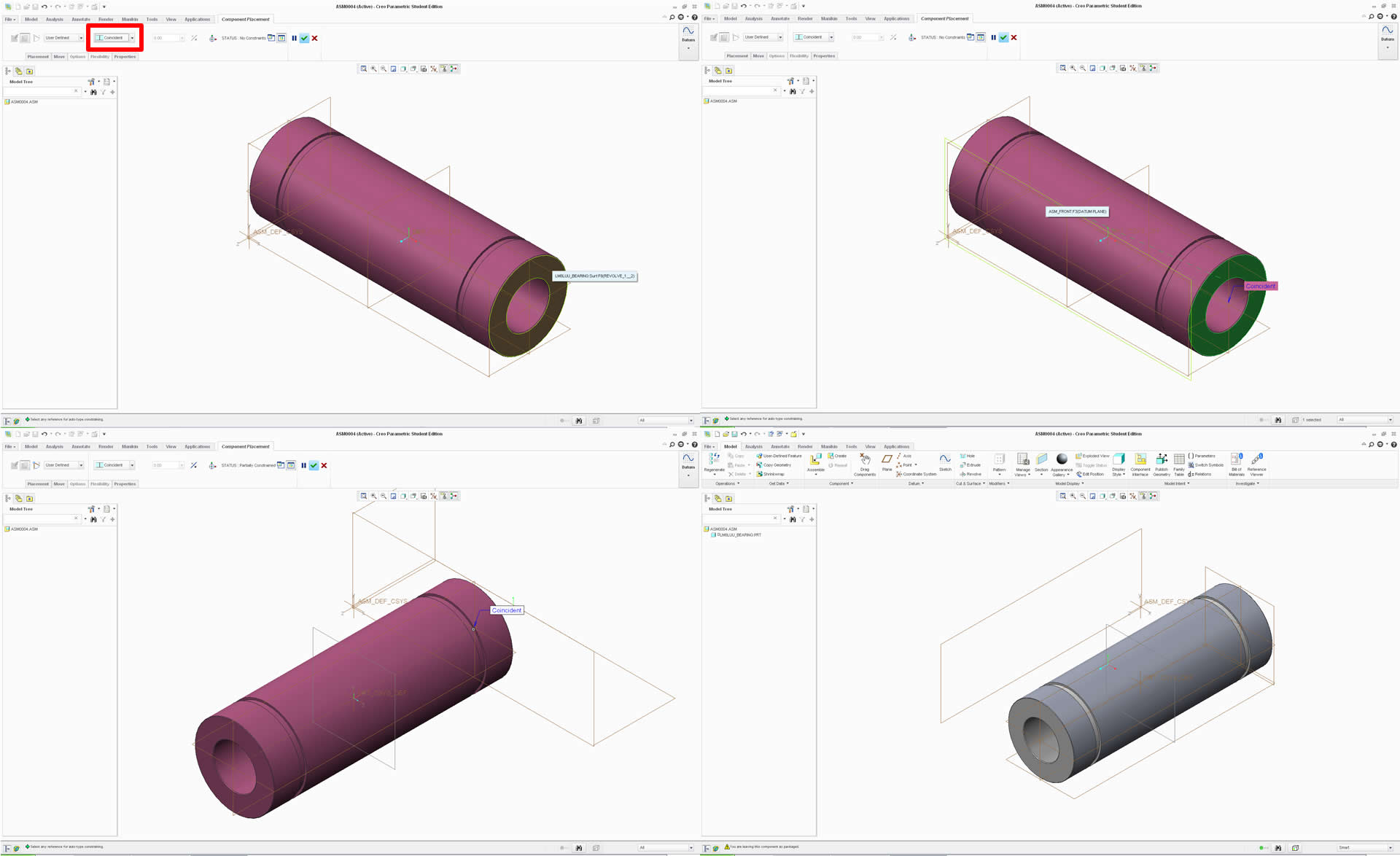
Oh Those were both perfect. Just did this in an assembly. Once the part was imported, I just used coincident to select the front face to the bearing and Front plane. Turned it just right. Here is a pic.

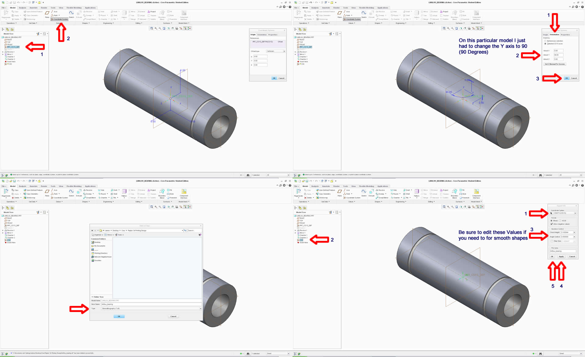
Also, it worked in just the part file, by assigning and newly created coordinate system as you suggested. Here is a pic.

Thanks for the help guys.
- Mark as New
- Bookmark
- Subscribe
- Mute
- Subscribe to RSS Feed
- Permalink
- Notify Moderator
Hi James.
As with most things Creo (was ProE) the answer is sort of.
Did you make your model with a coordinate system or default datum planes in it?
With either of these you can make an additional coordinate system relative to the first coordinate system or the datum planes and you can select which axis is called what and which way it is pointing at that time. Then call up this added coordinate system in your slicer program.
You can add a coordinate system just from orthogonal geometry too.
If you can only reference your base coordinate system then I am afraid you will have to recreate your geometry but I doubt that is the case.
Hope this helps.
Regards. Brent
- Mark as New
- Bookmark
- Subscribe
- Mute
- Subscribe to RSS Feed
- Permalink
- Notify Moderator
Hi Brent, Thank you for taking the time.
I am new to Parametric, however I am sure I simply selected "front" on the left pane and selected "sketch" in order to start building the part using lines, then revolve then mirror.
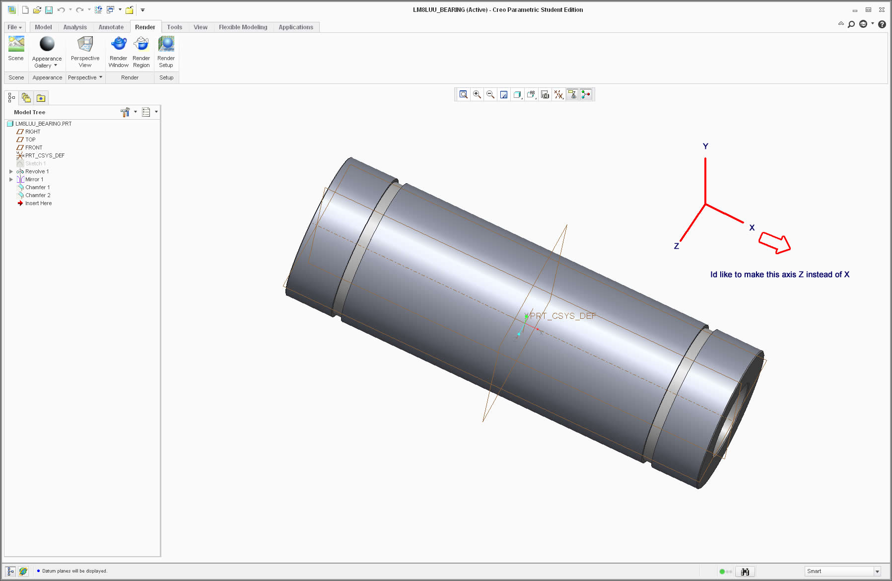
It is a linear bearing I created. I didnt know it at the time but the orientation matters when building from what I can tell, and this bearing has the z axis pointing to the side of the bearing vs parralel to the center shaft opening.
Is there a guide or a detailed way to turn the x axis into the z axis?
Attached is a pic of the way it is now.

- Mark as New
- Bookmark
- Subscribe
- Mute
- Subscribe to RSS Feed
- Permalink
- Notify Moderator
I am not sure what your slicer program is. In general, orientation of Creo parts doesn't matter since you can orient them any way you want in the assembly. When you export a file you often have the option to assign a different coordinate system to the export so you can orient the part at that point.
If you want to reconstruct the part, you can choose a different sketch plane for each feature. This will be some extra work but it can be done.
Last but not least, you can assemble the part into an assembly and orient the part with the correct Z in the assembly.
Again, it depends on what you are doing in how you want to change this part.
- Mark as New
- Bookmark
- Subscribe
- Mute
- Subscribe to RSS Feed
- Permalink
- Notify Moderator
Oh Those were both perfect. Just did this in an assembly. Once the part was imported, I just used coincident to select the front face to the bearing and Front plane. Turned it just right. Here is a pic.

Also, it worked in just the part file, by assigning and newly created coordinate system as you suggested. Here is a pic.

Thanks for the help guys.
- Mark as New
- Bookmark
- Subscribe
- Mute
- Subscribe to RSS Feed
- Permalink
- Notify Moderator
You are welcome... And thank you for detailing the process ![]()


