
Turn on suggestions
Auto-suggest helps you quickly narrow down your search results by suggesting possible matches as you type.
Showing results for
Please log in to access translation
Turn on suggestions
Auto-suggest helps you quickly narrow down your search results by suggesting possible matches as you type.
Showing results for
Community Tip - New to the community? Learn how to post a question and get help from PTC and industry experts! X
- Community
- Creo+ and Creo Parametric
- 3D Part & Assembly Design
- Re: Constraining Angular Motion of Ball Joint
Translate the entire conversation x
Please log in to access translation
Options
- Subscribe to RSS Feed
- Mark Topic as New
- Mark Topic as Read
- Float this Topic for Current User
- Bookmark
- Subscribe
- Mute
- Printer Friendly Page
Constraining Angular Motion of Ball Joint
Apr 04, 2021
10:49 PM
- Mark as New
- Bookmark
- Subscribe
- Mute
- Subscribe to RSS Feed
- Permalink
- Notify Moderator
Please log in to access translation
Apr 04, 2021
10:49 PM
Constraining Angular Motion of Ball Joint
Hello,
I'm creating a motion skeleton to model a motion platform similar to this:
https://www.youtube.com/watch?v=3tSbAjnCR18
As you can see, there are ball joint end rods that connect the motor arms to the platform. I was able to model them using ball joints, but by doing so, I am unable to limit the rod from deviating off the same plane of motion as the motor arms (does that make sense??).
I found a similar topic: https://community.ptc.com/t5/3D-Part-Assembly-Design/Constrain-Angular-Travel-of-Ball-Joint/td-p/185979. No one was able to give a solution but someone mentioned how I could use two perpendicular pins to control the range of motion between two perpendicular planes. I've been trying for a while to get it to work but I keep failing. Does anyone know how to accomplish this?
Thank you!
Solved! Go to Solution.
Labels:
- Labels:
-
Assembly Design
ACCEPTED SOLUTION
Accepted Solutions
Apr 10, 2021
03:31 AM
- Mark as New
- Bookmark
- Subscribe
- Mute
- Subscribe to RSS Feed
- Permalink
- Notify Moderator
Please log in to access translation
Apr 10, 2021
03:31 AM
Glad it worked out. It sounds like you had a good learning experience; for me, it affirmed that avoiding motion skeletons is the way to go.
If you are interested, I attached a toy model with the simple ball joints (gray) and the more complicated 3-pin-joint construction which allows angular limits in 2 directions (green):

7 REPLIES 7
Apr 05, 2021
03:15 PM
- Mark as New
- Bookmark
- Subscribe
- Mute
- Subscribe to RSS Feed
- Permalink
- Notify Moderator
Please log in to access translation
Apr 05, 2021
03:15 PM
Ball joint connections allow you to specify a "cone angle" type of motion limit. Does that not work for you?
Can you post a sketch explaining the constraints you require?
- Tags:
- you
Apr 08, 2021
12:04 AM
- Mark as New
- Bookmark
- Subscribe
- Mute
- Subscribe to RSS Feed
- Permalink
- Notify Moderator
Please log in to access translation
Apr 08, 2021
12:04 AM
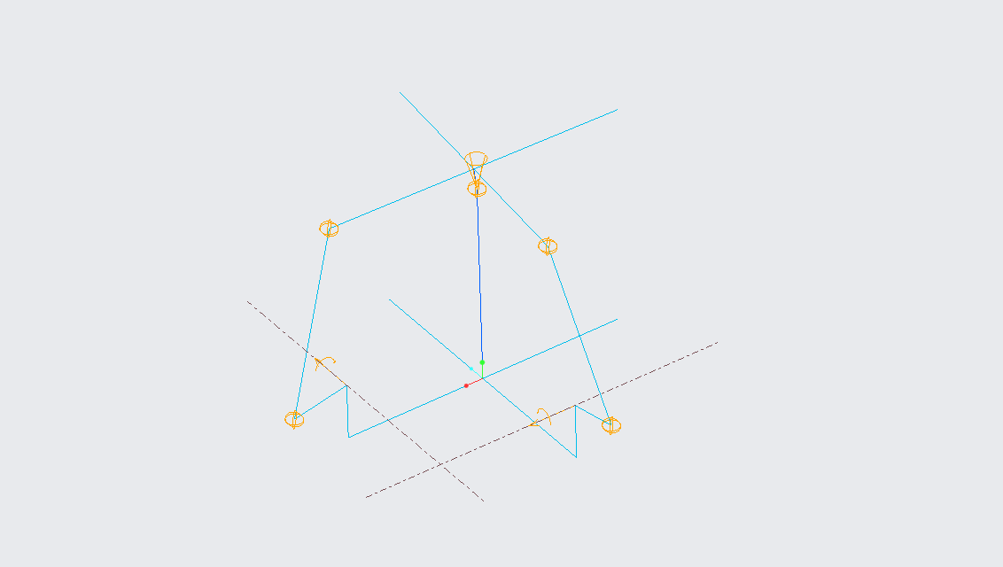
I attached a basic screenshot of the skeleton model. Please compare it to the youtube video in the original post if you can. Essentially there are 4 rod end ball joints (like these) that connect the motor arms to the platform. They give the platform some rotational wiggle room when the platform swivels, but don't allow for extreme angles due to how their connection with the motor arms are.
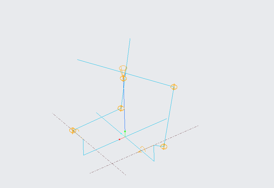
The first screenshot is a standard orientation for the table. The second is an example of the extreme rotation that occurs because the skeleton model's ball joints cannot be constrained, which is obviously not desired. You can see in the video that the supports move in the same plane as the motor arms, but only have so much room to move to the left and right of that plane.
Essentially I'm asking how the best way to simulate the ball joint rod ends in a motion skeleton. Does that make sense?
Apr 08, 2021
12:14 AM
- Mark as New
- Bookmark
- Subscribe
- Mute
- Subscribe to RSS Feed
- Permalink
- Notify Moderator
Please log in to access translation
Apr 08, 2021
12:14 AM
Sorry I didn't see your first question. I tried using the cone axis but it only lets me use an assembly reference for a link that is connected to the link with a ball joint rather than an assembly plane, like a pin's rotation constraint can be done (i.e. in the bottom left ball joint in the first screenshot, the component reference is the longest arm, and the assembly reference is the short arm connected to that joint).
Apr 08, 2021
12:19 AM
- Mark as New
- Bookmark
- Subscribe
- Mute
- Subscribe to RSS Feed
- Permalink
- Notify Moderator
Please log in to access translation
Apr 08, 2021
06:20 PM
- Mark as New
- Bookmark
- Subscribe
- Mute
- Subscribe to RSS Feed
- Permalink
- Notify Moderator
Please log in to access translation
Apr 08, 2021
06:20 PM
Sorry, I can't help much because I can't open your files (> Creo 4?)
Also, any reason for using motion skeletons? I consider them to be obsolete technology kept for legacy users.
I wouldn't use them, and so maybe there are limitations there that don't exist if constructing mechanisms in assembly context?
The cone angle seems to work well to simulate the physical limits of the ball end shaft hitting the edges of the mating socket. I imagine some ball joint designs allow/restrict more motion in one direction - in that case, you would need something more like elliptical cone, which does not exist in Creo. So, you end up constructing a kinematic ball joint out of 3 mutually perpendicular pin joints and place the angular limits on each axis' motion...
Apr 09, 2021
12:44 AM
- Mark as New
- Bookmark
- Subscribe
- Mute
- Subscribe to RSS Feed
- Permalink
- Notify Moderator
Please log in to access translation
Apr 09, 2021
12:44 AM
Ah sorry about the files, I'm using 6.0.
I'm actually a college student and very new to creo. Recently the class I am in introduced skeleton models for kinematic studies so I thought I would use them for this project. I mainly wanted to use it to play with the lengths of each feature to get an idea for how all the components move in relation to each other, not necessarily modeling parts directly through the skeleton.
I like the idea of using perpendicular pins, however, when you assign a sketch link as a pin joint, you can no longer assign that link for any other joint, thus why I'm stuck using a ball joint. If you have a solution for that then that would be cool!
Anyways, I resorted to giving up on the skeleton and downloading a rod end from grabcad. Eventually, after placing enough datum features, I properly set the cone angle relatively easily.
Apr 10, 2021
03:31 AM
- Mark as New
- Bookmark
- Subscribe
- Mute
- Subscribe to RSS Feed
- Permalink
- Notify Moderator
Please log in to access translation
Apr 10, 2021
03:31 AM
Glad it worked out. It sounds like you had a good learning experience; for me, it affirmed that avoiding motion skeletons is the way to go.
If you are interested, I attached a toy model with the simple ball joints (gray) and the more complicated 3-pin-joint construction which allows angular limits in 2 directions (green):


