Community Tip - Did you get called away in the middle of writing a post? Don't worry you can find your unfinished post later in the Drafts section of your profile page. X
- Community
- Creo+ and Creo Parametric
- 3D Part & Assembly Design
- Cosmetic threads in Creo 2
- Subscribe to RSS Feed
- Mark Topic as New
- Mark Topic as Read
- Float this Topic for Current User
- Bookmark
- Subscribe
- Mute
- Printer Friendly Page
Cosmetic threads in Creo 2
- Mark as New
- Bookmark
- Subscribe
- Mute
- Subscribe to RSS Feed
- Permalink
- Notify Moderator
Cosmetic threads in Creo 2
Hi.
I've searched but can't really find what I am looking for.
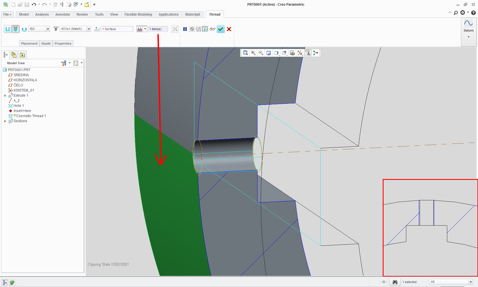
I'm having difficulties showing threads correctly on the drawing. Here are some screen captures to show what my issues are.
Here is what the cosmetic thread looks like on the model.
Here is what the cosmetic thread looks like on the drawing.
And here is what the .pdf file looks like when generated.
I do not want the vertical lines of the cosmetic threads to display. Is there a way to get rid of them or am I doing something wrong?
Thanks,
Jason
This thread is inactive and closed by the PTC Community Management Team. If you would like to provide a reply and re-open this thread, please notify the moderator and reference the thread. You may also use "Start a topic" button to ask a new question. Please be sure to include what version of the PTC product you are using so another community member knowledgeable about your version may be able to assist.
- Labels:
-
Data Exchange
- Mark as New
- Bookmark
- Subscribe
- Mute
- Subscribe to RSS Feed
- Permalink
- Notify Moderator
Make a cross section?

- Mark as New
- Bookmark
- Subscribe
- Mute
- Subscribe to RSS Feed
- Permalink
- Notify Moderator
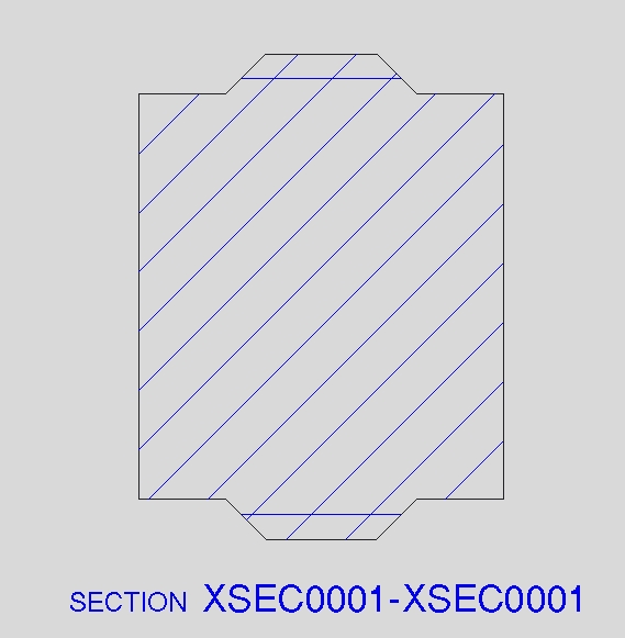
Here is what my section looks like.
Are there config options that I can change?
Thanks,
Jason
- Mark as New
- Bookmark
- Subscribe
- Mute
- Subscribe to RSS Feed
- Permalink
- Notify Moderator
I have threads on a part that are going through all. But when I bring the view into the drawing, the threads don't stop at the part, but continue on into space. Can someone help me figure out how to have this stop at the part's edge? Thanks, Dale
- Mark as New
- Bookmark
- Subscribe
- Mute
- Subscribe to RSS Feed
- Permalink
- Notify Moderator
Dale did you try selecting outer ring surface to define thread lenght?
Or maybe hole that you are using for thread is defined as blind with lenght greater then ring thicknes.

- Mark as New
- Bookmark
- Subscribe
- Mute
- Subscribe to RSS Feed
- Permalink
- Notify Moderator
After I posted and before I got your response, I tried redefining the holes to two planes that I created for start and stop points relative to the surfaces. This did not stop the threads from continuing on into space. This was created as a threaded holes all together with the hole
- Mark as New
- Bookmark
- Subscribe
- Mute
- Subscribe to RSS Feed
- Permalink
- Notify Moderator
Does the hidden line removal for quilts option still exist in Creo 2.0 ? (I'm using WF5)
If so, it could help you (View properties>View display>Hidden line removal for quilts)
- Mark as New
- Bookmark
- Subscribe
- Mute
- Subscribe to RSS Feed
- Permalink
- Notify Moderator
Surely after all these releases, now we are at the "Creo Revolution" a standard engineering feature like this should be handled correctly and should display properly in drawings.
PTC's failure to sort the countless deficiencies such as this is simply not good enough. I am seriously questioning my reasons for staying with Creo.
- Mark as New
- Bookmark
- Subscribe
- Mute
- Subscribe to RSS Feed
- Permalink
- Notify Moderator
MIGHT be able to erase the line under the layout tab, under line style. Why though? The line DOES exist because it's the start of the thd. Yes, it's not like doing it old school on the drafting board, but to me it's not a huge deal to see things like that on a dwg. I have my tangency lines set to phantom in most cases in dwg views, which is definately not old school, but I think adds to underestanding the organiclly sculpted shapes we have today.
Best of luck.
- Mark as New
- Bookmark
- Subscribe
- Mute
- Subscribe to RSS Feed
- Permalink
- Notify Moderator
Or depending on the end use, just cut the real helix on there. I know, not the fastest solution.
- Mark as New
- Bookmark
- Subscribe
- Mute
- Subscribe to RSS Feed
- Permalink
- Notify Moderator
PTC has been doing this for 35 years or so now. And we still have to deal with this crap?! Absolutely amazing! We are the idiots because we keep giving them money. In return we get endless frustration and poor productivity.
- Mark as New
- Bookmark
- Subscribe
- Mute
- Subscribe to RSS Feed
- Permalink
- Notify Moderator
I don't think you can turn the vertical lines off. I just leave them alone. Annoying as it is.


