
Turn on suggestions
Auto-suggest helps you quickly narrow down your search results by suggesting possible matches as you type.
Showing results for
Please log in to access translation
Turn on suggestions
Auto-suggest helps you quickly narrow down your search results by suggesting possible matches as you type.
Showing results for
Community Tip - Visit the PTCooler (the community lounge) to get to know your fellow community members and check out some of Dale's Friday Humor posts! X
- Community
- Creo+ and Creo Parametric
- 3D Part & Assembly Design
- Re: Creating a swept blend?
Translate the entire conversation x
Please log in to access translation
Options
- Subscribe to RSS Feed
- Mark Topic as New
- Mark Topic as Read
- Float this Topic for Current User
- Bookmark
- Subscribe
- Mute
- Printer Friendly Page
Creating a swept blend?
Jun 12, 2015
12:06 PM
- Mark as New
- Bookmark
- Subscribe
- Mute
- Subscribe to RSS Feed
- Permalink
- Notify Moderator
Please log in to access translation
Jun 12, 2015
12:06 PM
Creating a swept blend?
I have posted this question before but did not give enough information for an answer so here goes:
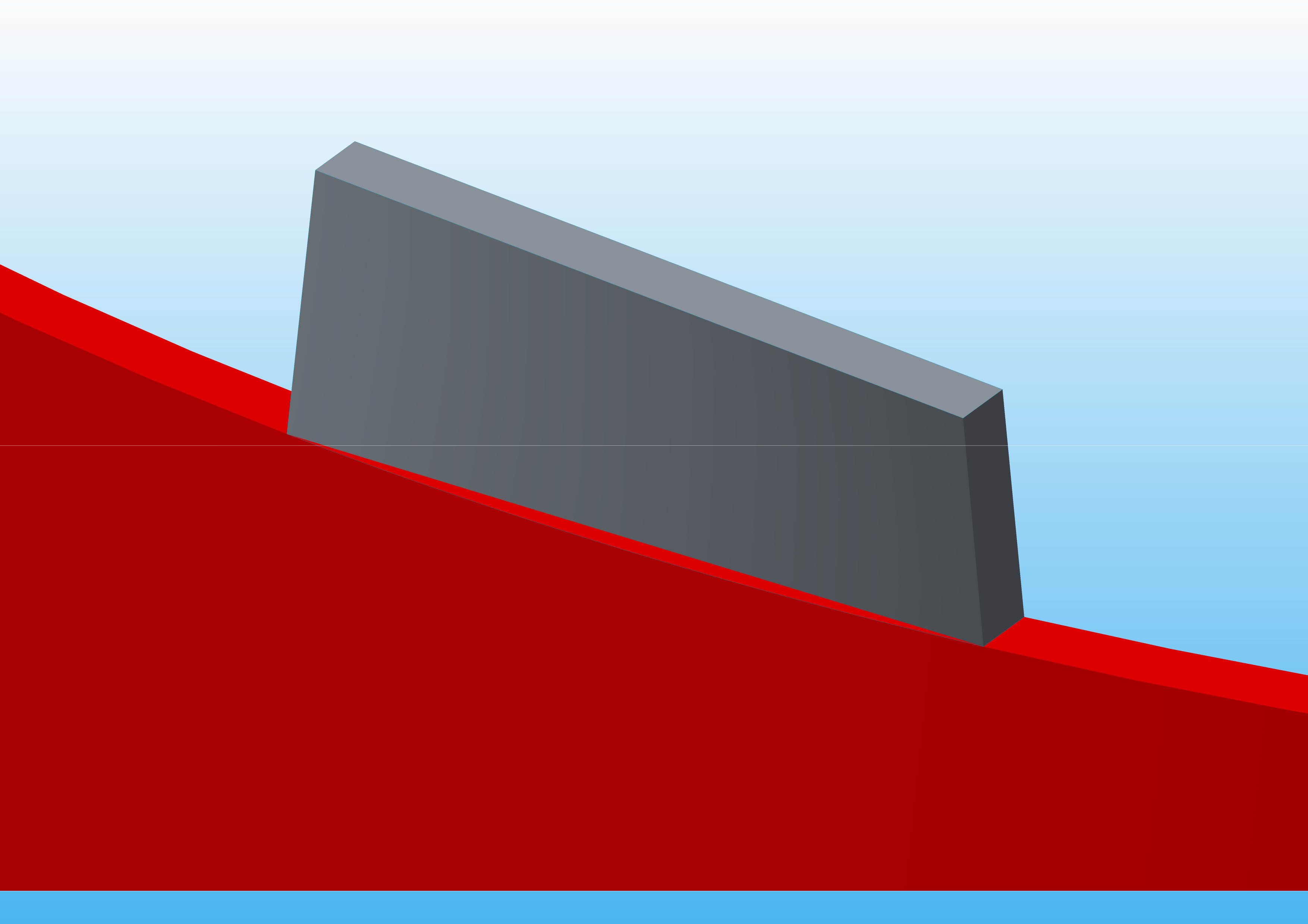
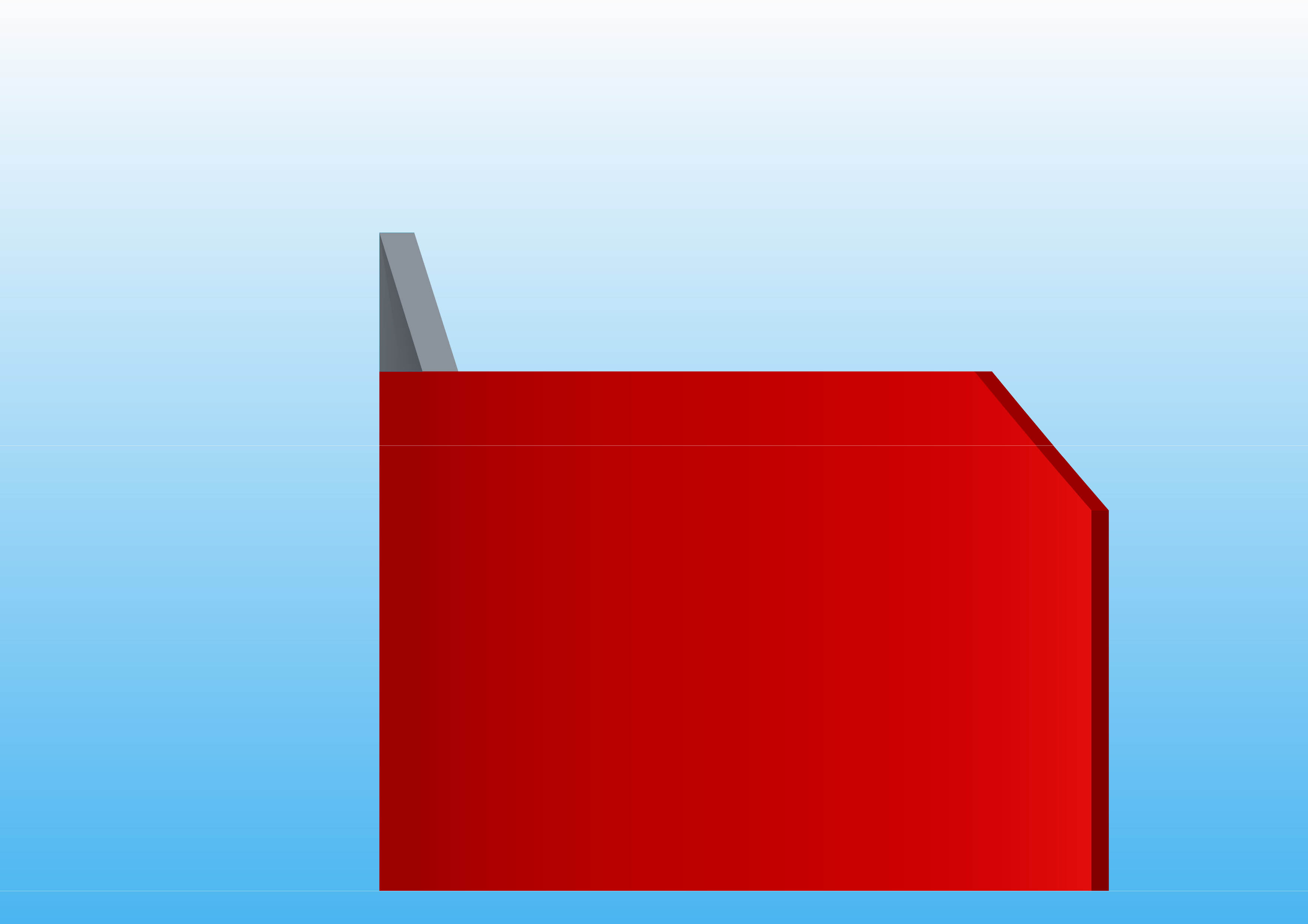
I want to create a swept blend from a parallelogram to a rectangle as shown by the blue lines in the attachment. The lower line to sweep is a curve but the upper line to sweep is a straight line. I have shown this in the attachment:
I am using Creo 2 in Windows 7 64 bit
I haven't done this before and if possible, will the finished sweep be a solid and can I then cut it?
This thread is inactive and closed by the PTC Community Management Team. If you would like to provide a reply and re-open this thread, please notify the moderator and reference the thread. You may also use "Start a topic" button to ask a new question. Please be sure to include what version of the PTC product you are using so another community member knowledgeable about your version may be able to assist.
Solved! Go to Solution.
Labels:
- Labels:
-
General
ACCEPTED SOLUTION
Accepted Solutions
Jun 15, 2015
03:51 PM
- Mark as New
- Bookmark
- Subscribe
- Mute
- Subscribe to RSS Feed
- Permalink
- Notify Moderator
Please log in to access translation
Jun 15, 2015
03:51 PM
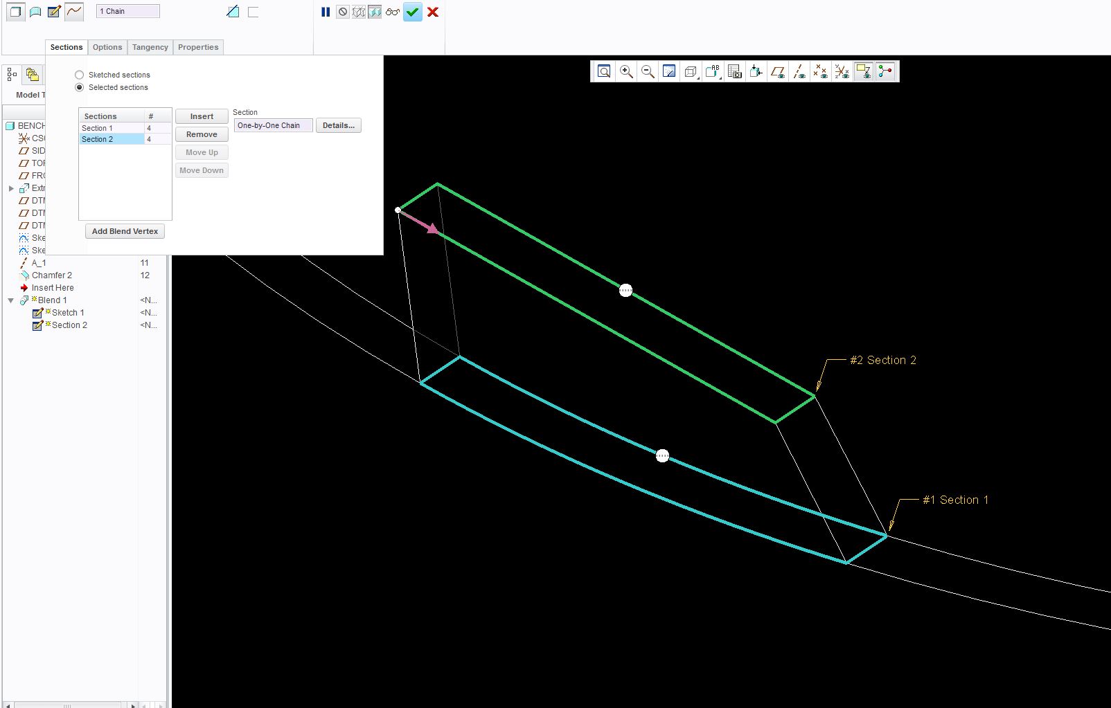
You have to align the arrows. The first picture is what you had. You can see one arrow on the left and one on the right, this will make the feature twist.
Also, in the second picture, you can change from Sketch to Select because you drew them already as Sketches. And same thing, just align the arrows to the same corners/same direction.

10 REPLIES 10
Jun 12, 2015
01:04 PM
- Mark as New
- Bookmark
- Subscribe
- Mute
- Subscribe to RSS Feed
- Permalink
- Notify Moderator
Please log in to access translation
Jun 12, 2015
01:04 PM
I did it with a blend and added the angled part after.
Jun 15, 2015
12:29 PM
- Mark as New
- Bookmark
- Subscribe
- Mute
- Subscribe to RSS Feed
- Permalink
- Notify Moderator
Please log in to access translation
Jun 15, 2015
12:29 PM
Hi Matt,
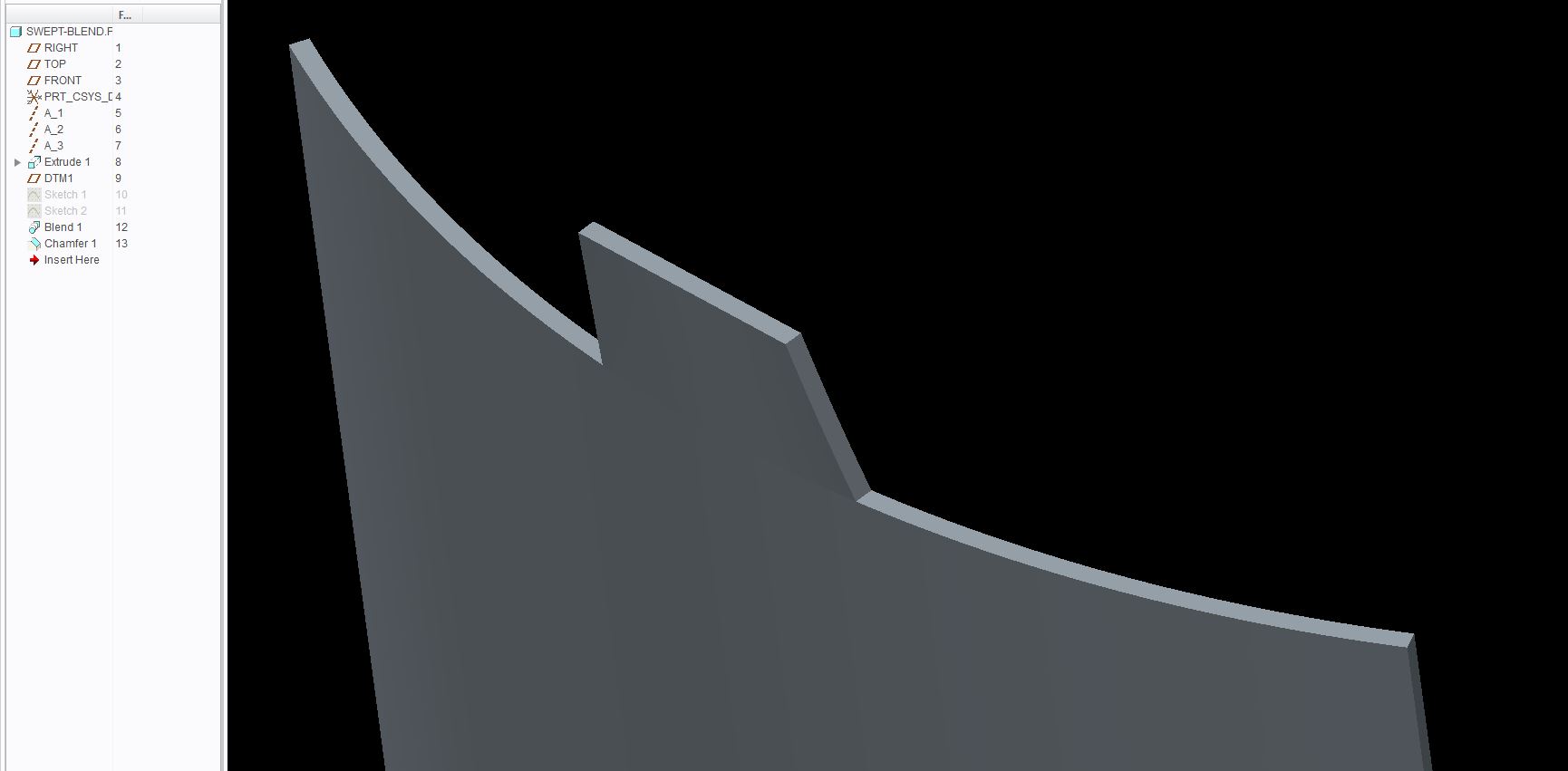
I can't seem to get the same blend as you have and not sure why. I have attached four images of half the tag (I was going to mirror the other half). What happens is that the blend follows a straight line. In my case the upper line is straight from box section to box section but the lower line is a curve. How did you do yours?

Jun 15, 2015
12:34 PM
- Mark as New
- Bookmark
- Subscribe
- Mute
- Subscribe to RSS Feed
- Permalink
- Notify Moderator
Please log in to access translation
Jun 15, 2015
03:11 PM
- Mark as New
- Bookmark
- Subscribe
- Mute
- Subscribe to RSS Feed
- Permalink
- Notify Moderator
Please log in to access translation
Jun 15, 2015
03:11 PM
This is what I get in the attached file. I have only done half the blend tag and will mirror the finished half:
Jun 15, 2015
03:51 PM
- Mark as New
- Bookmark
- Subscribe
- Mute
- Subscribe to RSS Feed
- Permalink
- Notify Moderator
Please log in to access translation
Jun 15, 2015
03:51 PM
You have to align the arrows. The first picture is what you had. You can see one arrow on the left and one on the right, this will make the feature twist.
Also, in the second picture, you can change from Sketch to Select because you drew them already as Sketches. And same thing, just align the arrows to the same corners/same direction.
Jun 16, 2015
06:59 AM
- Mark as New
- Bookmark
- Subscribe
- Mute
- Subscribe to RSS Feed
- Permalink
- Notify Moderator
Please log in to access translation
Jun 16, 2015
06:59 AM
Excellent! I was trying to remember how to move the arrows around and could not but eventually found that you could grab and manoeuvre them. Thanks a bunch for this. That's the problem with not using 3D CAD every day..........it's easy to forget the smallest things.
Jun 17, 2015
01:31 PM
- Mark as New
- Bookmark
- Subscribe
- Mute
- Subscribe to RSS Feed
- Permalink
- Notify Moderator
Please log in to access translation
Jun 17, 2015
01:31 PM
Boundary blends to the cylindrical surfaces might be better, if more work, because you can then specify boundary conditions. Does it really go to a strictly rectangular section there from the cylinder?
Jun 17, 2015
01:50 PM
- Mark as New
- Bookmark
- Subscribe
- Mute
- Subscribe to RSS Feed
- Permalink
- Notify Moderator
Please log in to access translation
Jun 17, 2015
01:50 PM
I agree with using boundary blends and then solidifying afterward. Boundary Blends give you much more control although can take more features and steps to get the desired result. As I have mentioned on other modeling issues, it is not how quick you get there initially, it is about getting the desired design intent that is also easily controlled and changed.
Jun 17, 2015
02:54 PM
- Mark as New
- Bookmark
- Subscribe
- Mute
- Subscribe to RSS Feed
- Permalink
- Notify Moderator
Please log in to access translation
Jun 17, 2015
02:54 PM
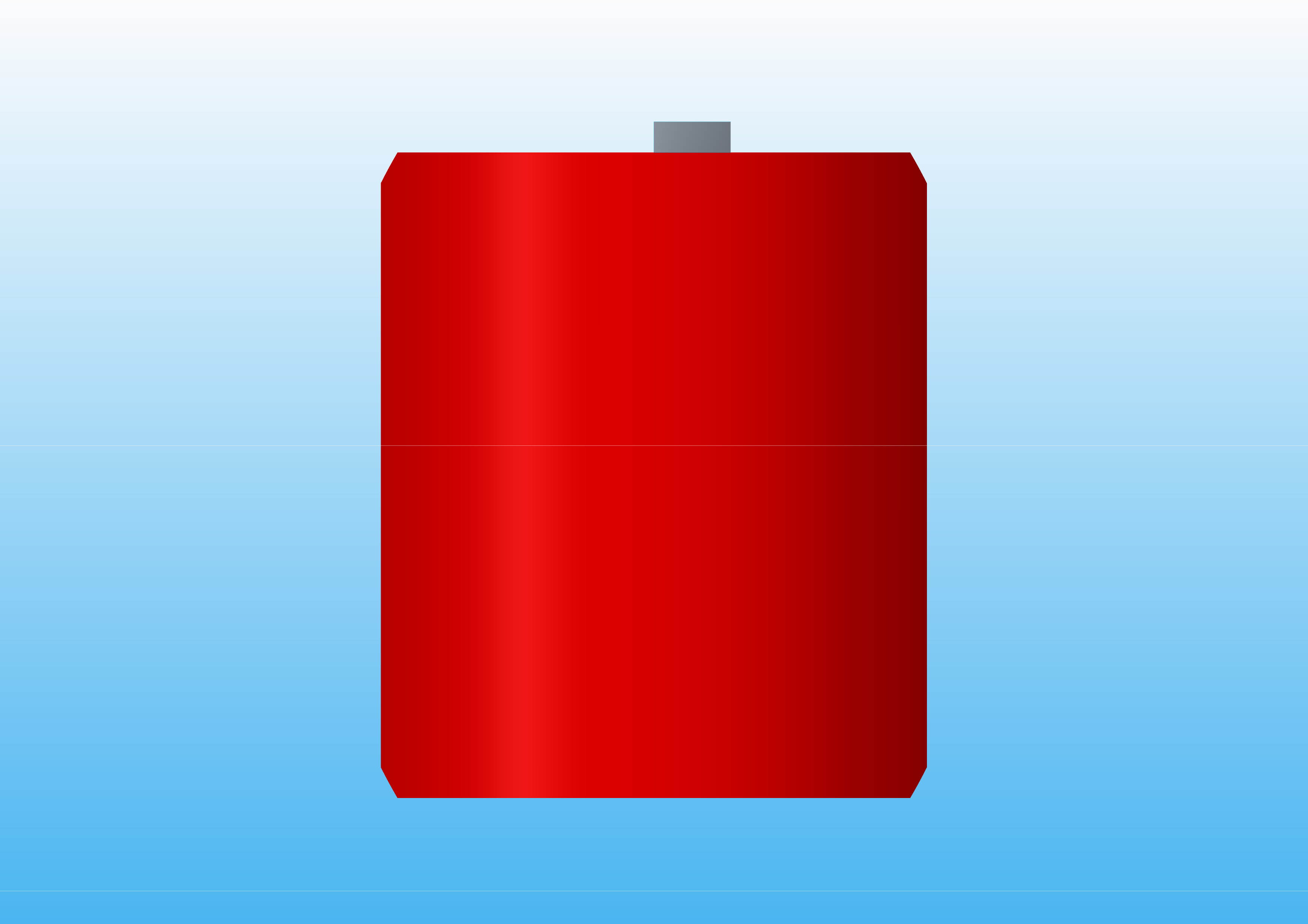
I've attached the final design. Wasn't sure if you could cut the section I created hence the direction I took. I'll bear your method in future though!
Thanks for your input guys.
Jun 17, 2015
03:11 PM
- Mark as New
- Bookmark
- Subscribe
- Mute
- Subscribe to RSS Feed
- Permalink
- Notify Moderator
Please log in to access translation
Jun 17, 2015
03:11 PM
Thanks for sharing the final design results. Good to know why the need. I am hooked on Boundary Blends!! 🙂


