
Turn on suggestions
Auto-suggest helps you quickly narrow down your search results by suggesting possible matches as you type.
Showing results for
Please log in to access translation
Turn on suggestions
Auto-suggest helps you quickly narrow down your search results by suggesting possible matches as you type.
Showing results for
Community Tip - Learn all about the Community Ranking System, a fun gamification element of the PTC Community. X
- Community
- Creo+ and Creo Parametric
- 3D Part & Assembly Design
- Re: Curve by equation / motion skeleton
Translate the entire conversation x
Please log in to access translation
Options
- Subscribe to RSS Feed
- Mark Topic as New
- Mark Topic as Read
- Float this Topic for Current User
- Bookmark
- Subscribe
- Mute
- Printer Friendly Page
Curve by equation / motion skeleton
Jan 19, 2022
03:23 AM
- Mark as New
- Bookmark
- Subscribe
- Mute
- Subscribe to RSS Feed
- Permalink
- Notify Moderator
Please log in to access translation
Jan 19, 2022
03:23 AM
Curve by equation / motion skeleton
Hello!
I need help to define curve with equation. I have simple loop as shown in the attachment.
I have the problem to guide a point /curve) on the loop.
Although, I use the loop curve at all as reference (and not jus a segment) and I can quide the point in the sketcher, the loop will be not identified by the motion skeleton.
I suppose, that if the curve is generate by equation, maybe it will run.
Can somebody write the equation for this loop?
Thank you!


www.pi-engineering.at
Solved! Go to Solution.
Labels:
- Labels:
-
Assembly Design
ACCEPTED SOLUTION
Accepted Solutions
Jan 21, 2022
11:30 AM
- Mark as New
- Bookmark
- Subscribe
- Mute
- Subscribe to RSS Feed
- Permalink
- Notify Moderator
Please log in to access translation
Jan 21, 2022
11:30 AM
Hello @PI_6131154
The way how you are tring to approach this cannot work directly, because would assume system being able to handle simulatenously:
- The Drag you want all along the curve (and currently, in your files, the reference of the slot connections can be only one arc -or a sgement - but not the whole curve)
- And especially, an "update" you would expect of the External Copy Geometry "shape" along drag operation (based on positions of points, on the arcs or on the segments)
And point 2 is not possible. Internal features of a given component is not supposed to change upon drag process (there is "no regeneration" upon "Drag" for obvious performance reasons). Only way to "change geometry of a component", based on assembly conditions, would be the notion of Flexibility, but related to that:
- I do not see any "good definition" which may be configured to satsify your constraint as par of the Flexibility Definition
- Even if there was one, a moveable or flexible component, such as springs, hinges, skeleton parts, or datums lock the referenced components to form one rigid body during dragging operations => Documented in Help Center here.
Above are all the reasons why I would approach this differently, using one single object (either a part or a skeleton) for each link of the chain. Better than a long explanation, I registered in attached movie (with sound for explanations ... sorry for my "french" accent) illustrating my suggestion for this use case.
Far from being sure that it's the best solution (if anyone has better ideas, thanks in advance to share them here), I hope this will help you at least a bit to make some progress in your ongoing project.
Regards,
Serge
35 REPLIES 35
Jan 19, 2022
08:52 AM
- Mark as New
- Bookmark
- Subscribe
- Mute
- Subscribe to RSS Feed
- Permalink
- Notify Moderator
Please log in to access translation
Jan 19, 2022
08:52 AM
Hello @PI_6131154
Looks more like a "math" question more than one related to CreoParametric capabilities. I searched in this direction but failed to find any Cartesian or Cylindrical equation producing this kind of geometry. Related to that:
- This post gives a list of useful equations to produce different shapes, but unfortunately none speaking about "slot holes"
- I "Google-searched" in this direction, but failed to find any relevant information on an eventual equation able to produce this kind of geometry in planes
So, if anyone has an idea on how this equation can be built (X & Y, with zero Z), any suggestions are more than welcome.
Otherwise, why not approaching this with:
- A simple sketch curve (the one you did, but without the datum point & CSYS)
- Create the Datum Point on curve (+ evetual other things like an axis and a CSYS based on point later if needed)?
Approaching this as suggested above will allow you to:
- Create the Datum Point referring the whole curve (and not the single sketched entities)
- Control exactly where should be the "Start" (by dragging the point where you want all along the whole curve)
- Control if you want a "ratio" or a "real distance" (from the "Start") for the location of the Datum Point along this given sketched curve
Regards,
Serge
Jan 19, 2022
11:18 AM
- Mark as New
- Bookmark
- Subscribe
- Mute
- Subscribe to RSS Feed
- Permalink
- Notify Moderator
Please log in to access translation
Jan 19, 2022
11:18 AM
If I understand what you are trying to do it can be accomplished using a slot constraint. This video demonstrates using a motion skeleton to define a motion path to constrain a component. The Creo 4 models are enclosed for reference if this is what you are trying to do. The key is to manually select all segments of the curve needed when defining the slot connection point on line constraint.
========================================
Involute Development, LLC
Consulting Engineers
Specialists in Creo Parametric
Involute Development, LLC
Consulting Engineers
Specialists in Creo Parametric
Jan 19, 2022
12:09 PM
- Mark as New
- Bookmark
- Subscribe
- Mute
- Subscribe to RSS Feed
- Permalink
- Notify Moderator
Please log in to access translation
Jan 19, 2022
12:09 PM
Hi!
Thank you very much for the proposal! It is hi interesting.
But I wish to have my design 100% as curves i the skeleton. At least I wish to design the chain-well (it will be 4 "pins" weel). That is way I try to do all from the scratch.
I have record what should be possible to do with the drag hand.
And further more, I wish also to have rotated well, but this I suppose will be hard.
www.pi-engineering.at
Jan 19, 2022
12:34 PM
- Mark as New
- Bookmark
- Subscribe
- Mute
- Subscribe to RSS Feed
- Permalink
- Notify Moderator
Please log in to access translation
Jan 19, 2022
12:34 PM
Your video looks like a chain drive or vehicle track from a kinematic perspective. I do not see any reason why you cannot do it with models that contain curves and datums rather than solid geometry. Keep in mind that motion skeletons may or may not be the best way to get there. You have the option to connect multiple skeletons (representing solid bodies in the mechanism) connected using mechanism constraints. It can be argued that this is a best practice for a top-down approach to mechanism design in Creo. This would bypass the application of a motion skeleton.
I think you may find this video useful as a guide.
https://www.youtube.com/watch?v=eFmXf52gbok
========================================
Involute Development, LLC
Consulting Engineers
Specialists in Creo Parametric
Involute Development, LLC
Consulting Engineers
Specialists in Creo Parametric
Jan 19, 2022
01:27 PM
- Mark as New
- Bookmark
- Subscribe
- Mute
- Subscribe to RSS Feed
- Permalink
- Notify Moderator
Please log in to access translation
Jan 19, 2022
01:27 PM
Hi!
I'm convinced, that I have to work forward wit top-down strategy. I have may works with motion skeletons and I'm excited from this functionality.
The reason to do not wish to use ready created objects is:
- I have to design this objects not just stand alone. They have to be the product of the kinematical design
- Using at least mechanism functionality is a postprocess and it comes after the models are designed. This means, I pass the design issue.
- mechanism is for me just a "show" effect, but is not the way WAY part is design exactly so
That is way, I tray to do this in the phase "development"
At least I have to design the chain and the chain will.
I wish to be the controller, not the watcher 🙂
www.pi-engineering.at
Jan 19, 2022
01:41 PM
- Mark as New
- Bookmark
- Subscribe
- Mute
- Subscribe to RSS Feed
- Permalink
- Notify Moderator
Please log in to access translation
Jan 19, 2022
10:04 PM
- Mark as New
- Bookmark
- Subscribe
- Mute
- Subscribe to RSS Feed
- Permalink
- Notify Moderator
Please log in to access translation
Jan 19, 2022
10:04 PM
?? you want a parametric equation for a slot? I've a feeling that is something that involves infinite number of terms to achieve the exact result. Anyway, all this wrangling to get the motion skeleton to behave. As if there is a chance... Have you verified that your motion skeleton works with a curve from equation, for example an ellipse?

I'm open to hear something that makes me change my mind, but I think motion skeletons are an obsolete, 2D technology that no one uses and PTC isn't maintaining anymore. I would stay away from them. Top-down skeletons and mechanism connections are not mutually exclusive - please see https://www.youtube.com/watch?v=rxHTBj7Ukd8

Developing your design with a "Skeleton" technique and using Mechanism Connection are not necessarily mutually exclusive.
Jan 20, 2022
12:57 AM
- Mark as New
- Bookmark
- Subscribe
- Mute
- Subscribe to RSS Feed
- Permalink
- Notify Moderator
Please log in to access translation
Jan 20, 2022
12:57 AM
Hi!
Thank you for the video! It is very close to this what I wish to do.
First...yes, motion skeleton works with curve done by equation. I have checked this.
Second....I do not belive that motion skeleton is obsolet. It is technic not to much in use.
At least, until I do not made all important kinematik design works, I do not like to make solid models.
The Video should be ok, but in my case the guiding around do loop schuld stack becaouse on the same reason.
We stil to look for way for quiding pont on loop what is working in the sketcher, in the motion skeleton and even more: to represent wheel with drag possibiliti and the will move the point on the loop.
Maybe we have to use also some relations for length as "way" for the wheel rotation as "way" length vor the moving of the point on the loop.
www.pi-engineering.at
Jan 21, 2022
11:30 AM
- Mark as New
- Bookmark
- Subscribe
- Mute
- Subscribe to RSS Feed
- Permalink
- Notify Moderator
Please log in to access translation
Jan 21, 2022
11:30 AM
Hello @PI_6131154
The way how you are tring to approach this cannot work directly, because would assume system being able to handle simulatenously:
- The Drag you want all along the curve (and currently, in your files, the reference of the slot connections can be only one arc -or a sgement - but not the whole curve)
- And especially, an "update" you would expect of the External Copy Geometry "shape" along drag operation (based on positions of points, on the arcs or on the segments)
And point 2 is not possible. Internal features of a given component is not supposed to change upon drag process (there is "no regeneration" upon "Drag" for obvious performance reasons). Only way to "change geometry of a component", based on assembly conditions, would be the notion of Flexibility, but related to that:
- I do not see any "good definition" which may be configured to satsify your constraint as par of the Flexibility Definition
- Even if there was one, a moveable or flexible component, such as springs, hinges, skeleton parts, or datums lock the referenced components to form one rigid body during dragging operations => Documented in Help Center here.
Above are all the reasons why I would approach this differently, using one single object (either a part or a skeleton) for each link of the chain. Better than a long explanation, I registered in attached movie (with sound for explanations ... sorry for my "french" accent) illustrating my suggestion for this use case.
Far from being sure that it's the best solution (if anyone has better ideas, thanks in advance to share them here), I hope this will help you at least a bit to make some progress in your ongoing project.
Regards,
Serge
Jan 21, 2022
11:58 AM
- Mark as New
- Bookmark
- Subscribe
- Mute
- Subscribe to RSS Feed
- Permalink
- Notify Moderator
Please log in to access translation
Jan 21, 2022
11:58 AM
Hi Serge!
Great! This is the way how to do it.
Yesterday i done it maybe bevor you, but now I'm happy to see same solution.
I have tried also with the approximately copy of the curve trajectory.
But I stack on the moving of MORE THEN ONE segment of the chain. This way the stone, stoping me!
Great!
Can you please contact me by my page, so I will be glad to have you in my network.
Greeting from Austria!
www.pi-engineering.at
Jan 21, 2022
12:12 PM
- Mark as New
- Bookmark
- Subscribe
- Mute
- Subscribe to RSS Feed
- Permalink
- Notify Moderator
Please log in to access translation
Jan 21, 2022
12:12 PM
Nice video!
Jan 25, 2022
12:36 PM
- Mark as New
- Bookmark
- Subscribe
- Mute
- Subscribe to RSS Feed
- Permalink
- Notify Moderator
Please log in to access translation
Jan 25, 2022
12:36 PM
This is pretty much what I did a few months ago, but there is always an issue with the last link and the first link where the pins axiis will NOT be exactly coincident. Worse, this will vary depending on how many links are on the end arcs. What I TRIED to do was make a spline curve describing the chain path in sketcher with a perimeter value DRIVEN by a series of straight lines that equalled the length of the chain. I was going to have one of the catenary curves change as you dragged the links around. This way the end pins of the links would always be coincident and the chain path curve itself would change as you dragged the links, more like what actually happens in real life. BUT as soon as you turn a series of curves in sketcher into a spline, you CANNOT snap to it, so, there went that idea. So, what I simply did was make a curve the combined length of the number of links, assign 2 slot constraints to the very first link, then 1 coincident (axis) constraint to each following link to the one ahead of it, then one slot constraint to the guide curve. This meant the end pin on the very last link and the first pin on the first link were not coincident. I took a measurement of the misalignment, added that length to the guide curve, and it made it a lot closer, but still it was impossible to be perfect since, as I mentioned, the curve itself should change while you drag the links, and it can't. I thought about trying to use a flexible part but with the constant regeneration required every time you tried to drag it... My models are here:
Jan 25, 2022
03:57 PM
- Mark as New
- Bookmark
- Subscribe
- Mute
- Subscribe to RSS Feed
- Permalink
- Notify Moderator
Please log in to access translation
Jan 25, 2022
03:57 PM
Hi!
You forgot maybe the files?
www.pi-engineering.at
Jan 25, 2022
04:09 PM
- Mark as New
- Bookmark
- Subscribe
- Mute
- Subscribe to RSS Feed
- Permalink
- Notify Moderator
Please log in to access translation
Jan 25, 2022
04:09 PM
LOL I forget stuff now that I'm old for sure, but nope, they're a ZIP file attached to the first post of that thread. I just checked and they're still there. Post up if there's an issue with them and/or any comments you have about the solution. As mentioned, you can't get it perfect, but I think this is as close as you'll get for the reasons I and the PTC guy mentioned above.
Jan 25, 2022
04:19 PM
- Mark as New
- Bookmark
- Subscribe
- Mute
- Subscribe to RSS Feed
- Permalink
- Notify Moderator
Please log in to access translation
Jan 25, 2022
04:19 PM
Yes.. to be close to the top is good enough 🙂
Here is a link from something what is very close to your problem, but is other issue. Anyway, after this you will know how to place chain chambers near to the zero accuracy.
https://www.youtube.com/watch?v=q8QA6zyKpG4&ab_channel=Creolessons
It is in Russian language, that is way, be careful.... is on very good teacher.
Greetings from Austria!
www.pi-engineering.at
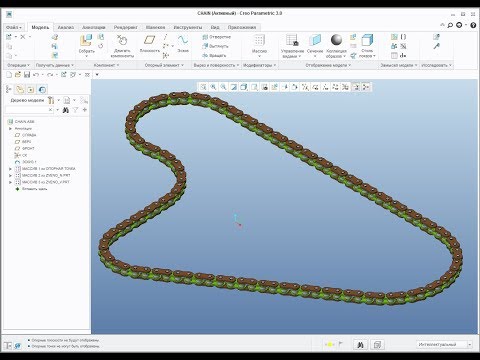
Вся коллекция уроков на сайте: https://engineer-center.ru/free-lessons/ Создание сборки цепи в Creo Parametric. Рассмотрены проблемы при сборке цепи и пути их решения. Показано использование нового инструмента "Периметр" для создания кривой натяжения цепи и продемонстрирован элемент адаптивности ...
Jan 25, 2022
06:42 PM
- Mark as New
- Bookmark
- Subscribe
- Mute
- Subscribe to RSS Feed
- Permalink
- Notify Moderator
Please log in to access translation
Jan 25, 2022
06:42 PM
I don't speak Russian, BUT, it looks like you cannot drag the links around, and I can't tell if the pins line up. Like I said, you cannot use a fixed length because of any arc in the path, just doesn't work. PLUS, what it looks like he's doing is basing the link length on the arc length, which is incorrect. Actual chain links are a fixed length from pin to pin, and you can't use an arc length because it doesn't match. So, while this video looks interesting, if I had the models I'm betting I can show you the geometry issues with it.
Did you look at the models?
Jan 31, 2022
02:36 AM
- Mark as New
- Bookmark
- Subscribe
- Mute
- Subscribe to RSS Feed
- Permalink
- Notify Moderator
Please log in to access translation
Jan 31, 2022
02:36 AM
Hello Serge!
I have please to you: can you please attach your files or check something for me.
It seems that the system has some limitations.
If my cahin-lien have 462.5mm, the loop has diameter of 1200mm and high more then 6300mm, it is not possible any more to move the chain.
Could you be so kind and verify this and in best case offer some tricks.
Thank you!
www.pi-engineering.at
Jan 31, 2022
03:14 AM
- Mark as New
- Bookmark
- Subscribe
- Mute
- Subscribe to RSS Feed
- Permalink
- Notify Moderator
Please log in to access translation
Jan 31, 2022
03:14 AM
Hello @PI_6131154
I'm currently unable to reproduce your issue. See movie attached (recorded in 7.0, but I checked retrieval in 8.0.2.0 and still works as expected) and assembly backed up at the end of the move here. Unless I missed anything, I used your dimensioning constraints (chain line: 462.5mm, loop diameter: 1200mm, linear length: 6300 mm), and evrything seems to work as expected (the chain of chain lines is dragging fine multipe times). Maybe, the issue you're facing is due either to accuracy settings, or to one of the mechainsm constraints not properly defined in one of the chain lines ... not sure.
Hope that movie and example attached will help anyway, not only to propose then final result, but especially for the approach used on the "repeat" actions (proposing a methodology to repeat the second line chain using ball + slot connections).
Regards,
Serge
Jan 31, 2022
03:23 AM
- Mark as New
- Bookmark
- Subscribe
- Mute
- Subscribe to RSS Feed
- Permalink
- Notify Moderator
Please log in to access translation
Jan 31, 2022
03:23 AM
Hi Serge!
Yes.. same problem. Please use your model and change the length from 6300 to 6400 and try to move.
www.pi-engineering.at
Jan 31, 2022
03:32 AM
- Mark as New
- Bookmark
- Subscribe
- Mute
- Subscribe to RSS Feed
- Permalink
- Notify Moderator
Please log in to access translation
Jan 31, 2022
03:32 AM
Hello @PI_6131154
Seems still working as expected. See new little attached movie (new dimension chosen during modify: from 6300 to 6500, but tested also 6400 with same success)
Not sure what I currently miss to repropduce the issue you're facing in your environment at this point.
- Which Version/Datecode are you using?
- Did you try after startup without using any config.pro and no toolkits (maybe one of your options is responsible of behavior you're currently facing?)
Regards,
Serge
Jan 31, 2022
03:42 AM
- Mark as New
- Bookmark
- Subscribe
- Mute
- Subscribe to RSS Feed
- Permalink
- Notify Moderator
Please log in to access translation
Jan 31, 2022
03:42 AM
Hm.. strange.. Yes.. it is working. Sorry, maybe I hade mistake.
Your model is working.
My model with the motion skeleton stops at 6300
www.pi-engineering.at
Jan 31, 2022
03:44 AM
- Mark as New
- Bookmark
- Subscribe
- Mute
- Subscribe to RSS Feed
- Permalink
- Notify Moderator
Please log in to access translation
Jan 31, 2022
03:44 AM
And.. you model stops also... when more than.... 10.000
There ist one not "good" limitation
www.pi-engineering.at
Jan 31, 2022
04:15 AM
- Mark as New
- Bookmark
- Subscribe
- Mute
- Subscribe to RSS Feed
- Permalink
- Notify Moderator
Please log in to access translation
Jan 31, 2022
04:15 AM
Hello @PI_6131154
I am able now to reproduce your issue when using 10 000 instead of 6300/6400. Modifyng absolute acccuracy of asm/prt does not help in this context. I do not see any config option which may improve this either (and get rid from current observed limitation). This seems definitely to be a candidate therefore for a SPR to be reported to R&D to get, if not a fix, at least an explanation of why we have current limitation (I personnaly do not have any unfortunately).
For this however, I cannot start from here. Process requires a case to be reported, an investigation to be done in TS (in addition to what I already tried to propose here, but not enough unfortunately), and if no solution after further investigation, creation of a SPR starting from the case.
Therefore, if you would like to bring this point to the attention of our developers, I suggest to open a case to PTC TS, attach data previously shared here, and describe the steps to reproduce as follows:
- Open asm
- Observe that Drag of the chain of PRT0001.PRT is possible multiple times around the driving curve (which is the expected behavior)
- Modify now the longest dimension of sketch 1 from 6300 to 10 000
- Try to Drag, and observe that drag mechanism is unexpectedly limited from start point to end point of the approximate curve id 51 (based on Sketch 1 geometry) used as reference for the placement of the prt0001.prt components (assembled multiple times)
Regards,
Serge
Jan 31, 2022
04:52 AM
- Mark as New
- Bookmark
- Subscribe
- Mute
- Subscribe to RSS Feed
- Permalink
- Notify Moderator
Please log in to access translation
Jan 31, 2022
04:52 AM
🙂 Serge!! 🙂 I got it.
Do not use the copied curve and do not use the loop at all. Use all curve chambers.. than you can have unlimited
Best regards!

www.pi-engineering.at
Jan 31, 2022
05:26 AM
- Mark as New
- Bookmark
- Subscribe
- Mute
- Subscribe to RSS Feed
- Permalink
- Notify Moderator
Please log in to access translation
Jan 31, 2022
05:26 AM
Perfect @PI_6131154 !!
Still not clear to me how you were able to select 4 elements in the slot assembly references, but I did not spend enougn time to get a good understanding on this.
Anyway, very good to know you were able to srt this out!!
Regards,
Serge
Jan 31, 2022
05:36 AM
- Mark as New
- Bookmark
- Subscribe
- Mute
- Subscribe to RSS Feed
- Permalink
- Notify Moderator
Please log in to access translation
Jan 31, 2022
05:36 AM
select first segment of the slot, than hold Ctrl. and select the rest. And... way this was working, I unterstand that is working also in motion sceleton .. whuuuuh.. it was really hard. But when we all try it, we get it! 🙂
www.pi-engineering.at
Jan 31, 2022
05:46 AM
- Mark as New
- Bookmark
- Subscribe
- Mute
- Subscribe to RSS Feed
- Permalink
- Notify Moderator
Please log in to access translation
Jan 31, 2022
05:46 AM
Hello @PI_6131154
Just tested and I confirm.
Still a mystery why this does not work when chosing approximate curve instead, but anyway, as long as you can reach the outcome you're expecting, it's probably useless to pursue the invetigsation further in the scope of the appraoximate curve.
Thanks a lot for this very interesting exchange!
Regards,
Serge
Jan 31, 2022
05:58 PM
- Mark as New
- Bookmark
- Subscribe
- Mute
- Subscribe to RSS Feed
- Permalink
- Notify Moderator
Please log in to access translation
Jan 31, 2022
05:58 PM
??? So PTC has no process for investigating such "mysteries" unless consumer complains about it via a case?
Doesn't this border on negligence given the evidence of anomalous behaviour has been presented in this thread and been reviewed and verified by a PTC representative?
Feb 01, 2022
03:09 AM
- Mark as New
- Bookmark
- Subscribe
- Mute
- Subscribe to RSS Feed
- Permalink
- Notify Moderator
Please log in to access translation
Feb 01, 2022
03:09 AM
Hello @pausob
It's for sure not a question of negligence. If this was, we would even not pursued exchanges on this. Main purpose of my participation here (not asked by my managers in PTC, but only based on my own initiative) is to help the community, because customer's satisfaction was my motor since my very first day I joined PTC, 24 years ago. My current bandwith allows me to participate those days, which is rare as a general rule, and therefore not sure I'll have the time to pursue my efforts later. Well ... I'll try to do my best anyway.
From the process standpoint, every company has his own process, and PTC also does. It is precisely because we have a process that we have to follow it. No choice for us. And this process is documented in Opening a Case section of our Customer Support Guide as follows:
For product families of Creo and Mathcad you will have two options to choose from (and the “Support Assistant” will propose which one should be best for your situation):
- PTC-Assisted Community Support
- Getting help from industry peers, supplemented by the assistance of PTC’s Support product experts within the public environment of PTCs Community
- If this option is chosen, the issue will be automatically posted into PTC’s Community in the corresponding forum and you will receive the link to this posting.
- Assisted Technical Support
- Assisted Technical Support from the PTC Support Team of Product Experts
- If this option is chosen A Support Case will be opened upon submission of all information and the system will issue you a unique case number in the format C#######, for example, C1234567, that you can later use to track the resolution of your issue.
The main difference between the 2 above channels is that only second one is dedicated to the tracking process of issues reported by customers to PTC Technical Support Department.
Considering above, related to this specific post:
- My understanding is that @PI_6131154 is happy with the aletrnate selection of references (from sketch curve) offering him a stable and robust solution (first channel of the support guide)
- But If I'm wrong, a case can be reported (second channel of the support guide), and a SPR will be raised later, with a severity which will be decided by customer who will report this to us (not only who have participated to it till now, but whoever read this post - even later - and would be interested by follow-up actions)
Hello @PI_6131154
Just for info from a technical perspective, I was surprised yesterday by the confusion related to the value of the longest dimension causing the issue to appear (you said 6300, then 6400, and we agreed together to consider issue as reproducible on both sides for a value of 10 000). I played a bit further this morning with that, and understood where this difference of behavior comes from when the approximate curve (and not the stable 4 sketched curve references) is used as reference for the Slot mechanism placament. The success/failure allowing the drag over the start/end point of the appoximate curve seems to depend on zoom factor:
- If zoomed in upon Drag, this works (even in the scope of 10 000, but dragging chain lines one by one over the end point)
- if zoomed out upon Drag, the drag stops at end point of the approximate curve (could occur also for 6300, if zoomed out upon drag attempt)
- And higher is the model size, more the Zoom factor has to be increased to allow "passing the end point of the approximate curve" upon drag process
If a case will be reported in this direction (now or later), I think therefore that mentioning "zoom factor" has value to be documented to help investigation process in TS Department, and orient R&D in the good direction later on when raising SPR on this.
Last thing: if a case will be reported in the future (by you or whoever wants), don't hesitate to mention this post URL or even my name, and this will be my pleasure to take ownership of the case and handle it (and report the SPR accordingly).
Regards,
Serge


