Community Tip - Did you know you can set a signature that will be added to all your posts? Set it here! X
- Community
- Creo+ and Creo Parametric
- 3D Part & Assembly Design
- Re: Datum features & datum frames/targets
- Subscribe to RSS Feed
- Mark Topic as New
- Mark Topic as Read
- Float this Topic for Current User
- Bookmark
- Subscribe
- Mute
- Printer Friendly Page
Datum features & datum frames/targets
- Mark as New
- Bookmark
- Subscribe
- Mute
- Subscribe to RSS Feed
- Permalink
- Notify Moderator
Datum features & datum frames/targets
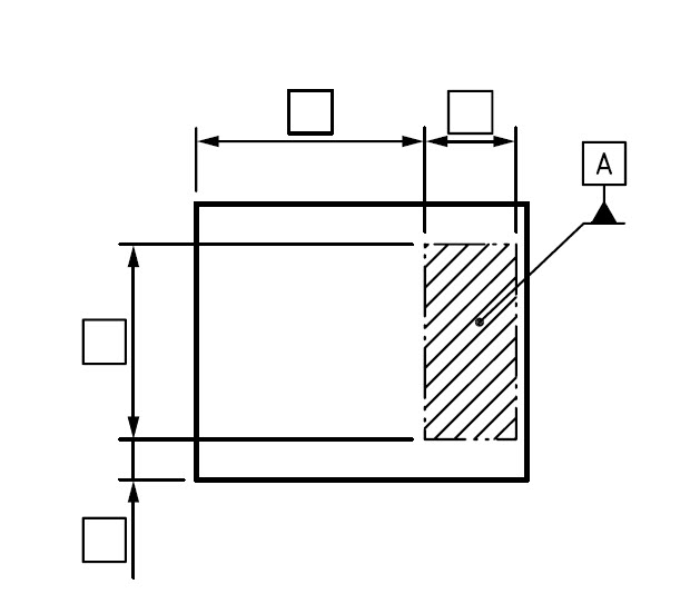
Hi, I can't get Creo to show the datum feature the way I like, I have a single datum frame/target on a part and will like to simplify the indication as shown in the picture below (ref, ISO 5459). Anybody know if this is possible?

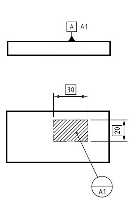
The only way I can achieve a result that comply with ISO 5459 in my situation is if I show the datum feature indication in another view/projection, attached to the surface, then uses a datum frame/target. The issue I have with this is that I can not find a god solution regarding adding the datum target name/number (A1) close to the datum feature indicator, as shown below. Sure I can add a note, but since I can not relate this note to the datum feature, it is not a robust metode....

Any good ideas?
This thread is inactive and closed by the PTC Community Management Team. If you would like to provide a reply and re-open this thread, please notify the moderator and reference the thread. You may also use "Start a topic" button to ask a new question. Please be sure to include what version of the PTC product you are using so another community member knowledgeable about your version may be able to assist.
- Labels:
-
General
- Mark as New
- Bookmark
- Subscribe
- Mute
- Subscribe to RSS Feed
- Permalink
- Notify Moderator
I don't think what you want to do is the proper representation of datum targets.

This is an image from the this link. He uses the 5459 standard and you can see that for datum target area you use the datum target symbol with a leader to the perimeter of the area and no arrow. For the side view of the part you would use the datum.
- Mark as New
- Bookmark
- Subscribe
- Mute
- Subscribe to RSS Feed
- Permalink
- Notify Moderator
Hi, thanks for the reply...
I don't know if you have read the ISO 5459:2011 standard, but this clearly states that the representation I want (first pic. in original post) is a correct simplification of the drawing indicator whenever there is only one datum target. This is the way I want it to show, but I can not achieve this in any good and robust way in Creo (the picture is actually a copy from the ISO 5459:2011 standard). So in the pic you are refereeing to, this method would only be valid for datum target C1, but they have chosen to show the drawing indicator in the traditional way.
Regarding the leader with or without dot/arrow and termination of this;
- When it is a datum target point or line (on a not hidden surface) you can terminate the solid leader with or without an arrow, if datum target is on a hidden surface the leader should be dashed and terminated with no arrow
- When it is a datum target area (on a not hidden surface) it should be a solid leader terminated with a dot, if the datum target is on a hidden surface the leader should be dashed and terminated with an open circle.
Also, in the pic, and link you are referring to do not comply with Rule 4 of ISO 5459:2011;
If a single datum feature is established from one or more datum targets belonging to only one surface, then
the datum feature identifier identifying the surface shall be repeated close to the datum indicator, followed by
the list of numbers (separated by commas) identifying the targets (see Figure 20). Each individual datum
target shall be identified by a datum target indicator, indicating the datum feature identifier, the number of the
datum target and, if applicable, the dimensions of the datum target.
This is actually my other issue, since I can't figure out a way do the simplified drawing indication, I am left with the traditional way, but I can not find any good and robust way of complying with Rule 4, the only way I can see is by adding the datum feature identifiers in a note, and placing this close to the datum indicator... which is not a good practice, especially since I can not relate this note to the datum indicator.
However, I see that the web page was last updated in 2010, and the latest version of ISO 5459 is from 2011, so the info on the web page may be a former practices.
I am quite sure that the representation I want is complying with ISO 5459 as stated above, but please feel free to bring inputs regarding this.
But first and moast I am looking for ways to actually show and do this in a Creo drawing, in a robust and easy way, which I am at the moment strouggeling to find...
- Mark as New
- Bookmark
- Subscribe
- Mute
- Subscribe to RSS Feed
- Permalink
- Notify Moderator
If this is created as a datum curve feature in the model, then it would at least be robust. Being parametric, the height of the leader and the location could be adjusted easily, unlike a symbol.
I hope someone has a better suggestion.
- Mark as New
- Bookmark
- Subscribe
- Mute
- Subscribe to RSS Feed
- Permalink
- Notify Moderator
If this is created as a datum curve feature in the model, then it would at least be robust. Being parametric, the height of the leader and the location could be adjusted easily, unlike a symbol.
I am not sure if I really follow you here... Are you talking about the simplified indication? Yes, I could create a datum curve or sketch to create the "leader", and this will be robust (though, it is not a leader it is a datum curve). Also, to have the Datum Feature Indicator located on the end of the "leader" I would need to create a plane here to relate the Datum Feature to, meaning that the Datum Feature indicator is not related to the surface I am actually want it to relate to... There may be an other way for this, placing the symbol on one reference but actually have the feature referring to another reference? As I do think this will cause an issue if you for instant should try to do a tolerance analyses...
However, I am (for now) somewhat OK with the simplified indication I really want not beeing possible to achieve, but the traditional indication should be possible. All I actually need is a good an robust way of displaying the datum feature indicators, in my opinion these should automatically appear close to the Datum Feature Indicator as shown in the picture:

But if I would have to insert them manually this would be OK as long as they are related to the Datum Feature Indicator in the drawing. Maybe this is possible with a custom Datum Indicator (if this is possible to use/implement)?
- Mark as New
- Bookmark
- Subscribe
- Mute
- Subscribe to RSS Feed
- Permalink
- Notify Moderator
I was suggesting creating a sketched datum curve feature in the model that looks like a Datum Feature Indicator with the A1, A2, A3 as text as part of it and not using the automatic symbol that PTC generates that doesn't work correctly.
Essentially, draw the symbol in 3D where it should appear, just like it would have been drawn by hand on a paper drawing.
- Mark as New
- Bookmark
- Subscribe
- Mute
- Subscribe to RSS Feed
- Permalink
- Notify Moderator
Thanks for the reply... your suggestion will sure make it look correct in the drawing, but still, this is not a solution, it is a work around.
I would really like if PTC could bring forward a solution that would let us create drawings that complies with the ISO standards in a robust and easy way, keeping us from inventing different ways to work around problems.


