cancel
Showing results for 
Search instead for 
Did you mean: 
cancel
Showing results for 
Search instead for 
Did you mean: 

Community Tip - If community subscription notifications are filling up your inbox you can set up a daily digest and get all your notifications in a single email. X

Did You Know? How to Use Motion Skeletons to Quickly Design Mechanisms

tmckeown
5-Regular Member

Did You Know? How to Use Motion Skeletons to Quickly Design Mechanisms

In our new “Did You Know” series we’ve discussed how to create advanced round geometry and tips for fewer model failures with Intent References, both in PTC Creo Parametric. This week Moshe Baum, Product Manager at PTC, tells us how to use motion skeletons to quickly design mechanisms in the PTC Creo Parametric Advanced Assembly Extension.


In this example, we will be using the initial design skeleton for an elliptical exercise bike and bring it to life.


Step 1:


First, define the ground body by selecting the curves that define it. The selected entities are automatically copied to the skeleton body as an external copy geometry feature. You can add more skeleton bodies using the same process.

                                DYK Motion Skeletons. Img 1.png

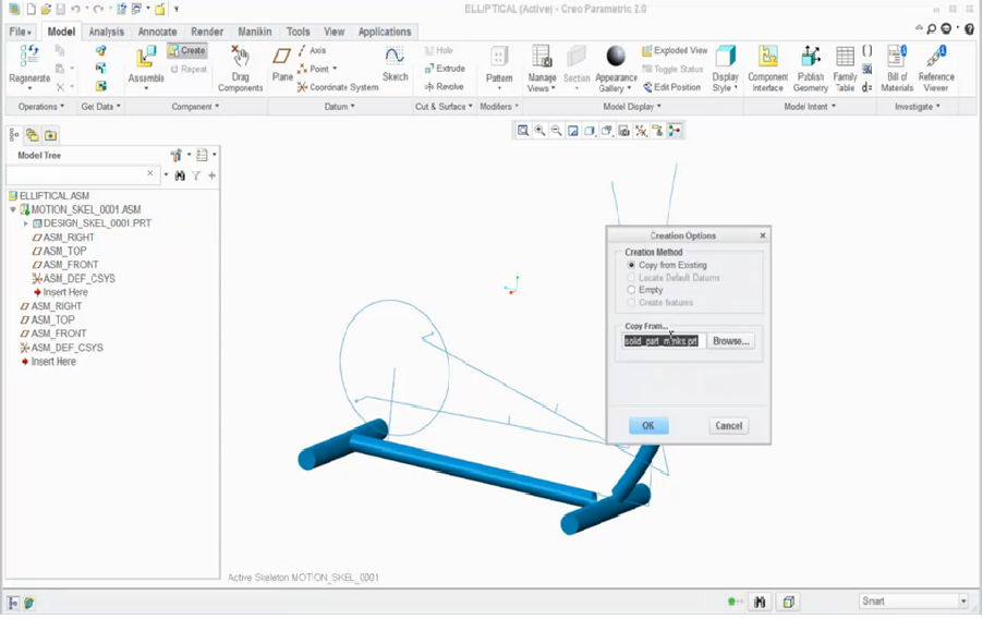
Adding skeleton bodies after defining the ground body by selecting its curves


Step 2:


Once again, select the entities that define the body. Click Update and the system automatically creates the potential connections according to the identified intersections of the curves that define the bodies. You can always change the definition of a switch to classic positioning mode. Let’s go ahead and define the rest of the bodies.


DYK Motion Skeletons. Img 2.png
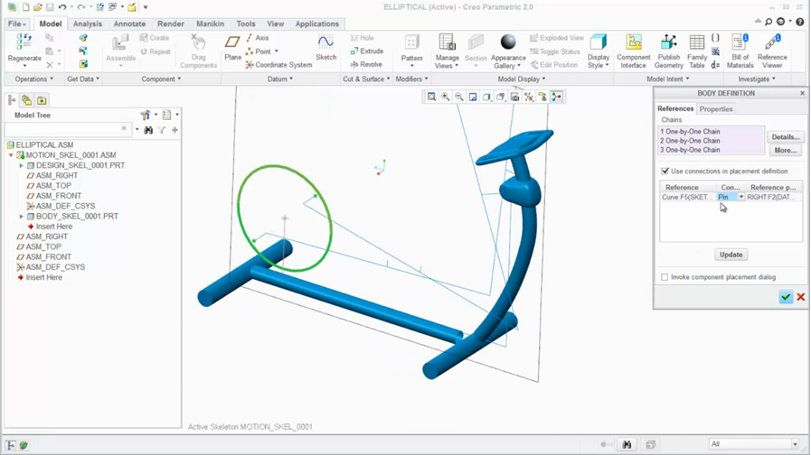
After clicking Update, the system automatically creates the connections


Step 3:


After we identify all the bodies and connections, the mechanism is now functional in the skeleton level. You can even perform a kinematic analysis in this early stage before designing a single part.


DYK Motion Skeletons. Img 3.png
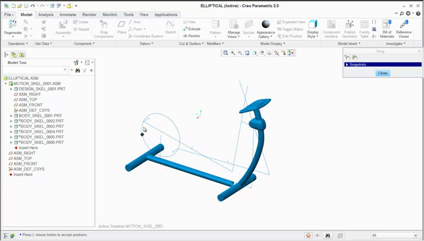
The functional mechanism at the skeleton level.


Step 4:


Time to start designing new assembly parts! When creating new parts, select Attached to Skeleton Body. This will place the new part on the same coordinate system of the selected body. It will also automatically populate the new part with a merge feature that contains the entire geometry of the selected body.


We can open parts and add detailed design around the entities that came from the top skeleton.


After a short while, we get a complete model that materializes the original design intent into a smart, fast, and automated top-down design.


DYK Motion Skeletons. Img 4.png

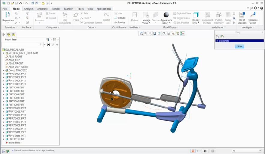
The final model: a smart, fast and automated top-down design.


Check out our video tutorial on the PTC University Learning Exchange (“Motion Skeletons”) to see this advice in action. We’d also love to hear your suggestions for working with motion skeletons below.


For more in-depth product feature explanations, visit our Tech Tips area.


Have some ideas about what PTC Creo product features you’d like to learn more about? Send me a message or leave a comment below and we’ll write up the best ideas from the community. Thanks for reading, looking forward to all of your feedback!


8 REPLIES 8
bp
6-Contributor
6-Contributor
(To:tmckeown)

When the solid bodies are attached to the skeleton bodies, there will not be any reaction forces available in these solid bodies when doing a force analysis in Mechanism Dynamics, because all connections are in the motion skeleton or am I missing something?

Also, in product development the designer tends to try to improve an initial design. This is hard enough using a standard skeleton.

In motion skeleton, if you add features to your standard skeleton, you have to link these manually to the right body skeletons. If you remove or even change a feature, you are going to have to be very patient and understanding..

This tutorial has obviously arisen out of a lot of hard work and thought, for which you are to be congratulated.

However, it fits into the same mould as most of the Pro/E Help and Tutorials that I have ever seen: That is to say, it instructs the student, given a set of models, to click a specific set of icons and watch a specific outcome arise. It makes no attempt to explain the reasoning behind the way the models were set up, or the choice of menu picks.

As a result, when I, for example, attempt to re-create the scenario in WF4, I have no way of knowing, based on this tutorial alone, what should be the relationship between the individual curves in the Design Skeleton. I define the ground body skeleton and when I hit update on my next body skeleton, a pin joint is created between the two curve ends. But, when I try to drag the 2nd body, I get the message 'You may not drag a body belonging to the ground body'. I wish I had a pound for each time I saw that message...

I'm sure that there is a very simple reason for this error message and that I am doing something fundamentally incorrect. That's OK and I will track it down and fix it. The point is that the tutorial provides only a 'best-case' scenario, with no assistance aimed at avoiding the plethora of available 'less-than-best-case' scenarios, or at rectifying them when they arise.

I just think that the whole of PTC is missing, and has always missed, a trick when producing tutorials like this.

There is a difference between a slick demo (in which only the 'best-case' scenario should be presented) and a tutorial (which is ostensibly aimed at enabling real-life users to address real-life scenarios).

This is very much not intended as a rant, nor as a criticism of you, Moshe. I would just like to see a relatively minor change in the direction in which tutorials are aimed, in order to make a significant increase in their usefulness. I am intending to be constructive...

John

BJ P,

You can definately get reactions forces on parts that are attached to skel bodies since ridigly connected bodies behave like single kinematic body. So you use same motion axis (in this case - the one in the motion skeleton) and get the reactions you want on the attached parts.

For example - here's reaction forces on one of the joints to the leg platforms:

Image.png

As for evoloving the design - Motion Skeleton allows you to create and evaluate very quickly different mechanism ideas.  You can always update the bodies by redefining them and re-evaluating connections.  Of course if mechanism layout dramatically changes - you may need to redefine many of the skeleton bodies. That is far mroe efficient to do so ealy on in skeleton stage, than when having fully details mechanism parts already designed.

-Moshe Baum

John,

Thanks for your comment and feedback.

I agree that Top-Down design in general, and Mechanism design in particular - naturally involve sometimes relatively complex scenarios and require fore-planning and good supporting training material, with as many realistic use cases as possible. This video and post was mainly purposed to draw attention to cool and usful functionality that many users are not aware of, but it is indeed only a subset of the full story and not as detailed as dedicated training material.

There is more detailed infromation available, espacially in PTCU/eLearning:

T3904-390-02   Advanced Assembly Design using Creo Parametric 2.0

Advanced Assembly Design using Creo Parametric 2.0 > Creating and Using Assembly Structure and Skeletons > Creating a Motion Skeleton > Lecture

Moving forward we will also continously add content to Learning Exchange, to better clarify and examplify tips and workflows in more details.

-Moshe Baum

Moshe,

The PTC eLearning tutorial you refer to suffers from the same problems that John alluded to, namely it is a step-by-step set of instructions with no explanation for why.  The student has to infer as best they can why things are done a certain way.

Hello Moshe BAUM,

i use PTC since many years but i still search about two answers:

-how could we create  a motion skeleton with two sketches in two perpendicular planes ?

-what way do you suggest to design a new product with a motion skeleton and sub-assemblies instead bodies attached to parts like in this tutorial

where we can see 12 parts in the tree ?

thank you for your answer

regards

francois

skesavan
4-Participant
(To:tmckeown)

Hi TMCKEOWN,


I am going to calculate the bucket available force as showing image (Bucket cylinder force we know 700kN) without creating all linkage parts because it consume lot of time to create the parts. It means it is possible to calculate force thought skeleton sketch?


Following Force need to calculate

Max available Bucket force

Max available Link -1 force

Max available Link -2 force


2019-03-25 09-48-29_Start.jpg

dhermosillo
13-Aquamarine
(To:tmckeown)

The "Tech Tips" link, at the bottom of the page, is broken.

Top Tags