Community Tip - Learn all about PTC Community Badges. Engage with PTC and see how many you can earn! X
- Community
- Creo+ and Creo Parametric
- 3D Part & Assembly Design
- Dimension between two views of a plane
- Subscribe to RSS Feed
- Mark Topic as New
- Mark Topic as Read
- Float this Topic for Current User
- Bookmark
- Subscribe
- Mute
- Printer Friendly Page
Dimension between two views of a plane
- Mark as New
- Bookmark
- Subscribe
- Mute
- Subscribe to RSS Feed
- Permalink
- Notify Moderator
Dimension between two views of a plane
Hello,
I explain my problem to you:
I need to make a 1: 1 scale plan template, the problem is that when my parts are too big, when I use my plan template, all my plans overlap (I don't know where is the left or right view) and I have to replace them by hand
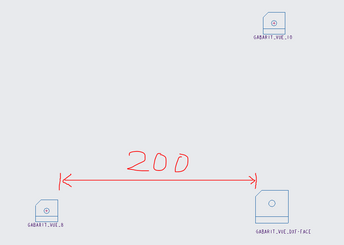
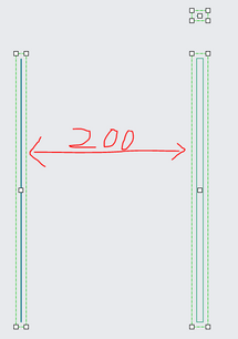
So I wanted to know if it was possible to be able to give a distance between the GABARIT_VUE?
I give you captures of what I imagine
(in the creation of the template plan)
(what it would look like with a piece)
Thank you so much
Maxence
Solved! Go to Solution.
Accepted Solutions
- Mark as New
- Bookmark
- Subscribe
- Mute
- Subscribe to RSS Feed
- Permalink
- Notify Moderator
It's exactly that @kdirth
And I think I found a more or less acceptable solution
I will overlay all my view templates in the same place (front, top and left plane)
Create a macro that will make a special shift of my left and top view from their current position. In their respective axis and the value that the macro will enter will be for the left view [the total width of the room * 1.5] and for the top view [the total height of the room * 1.5]
I will take the test and if you have any ideas for improvement or another method, please do not hesitate.
Thank you
- Mark as New
- Bookmark
- Subscribe
- Mute
- Subscribe to RSS Feed
- Permalink
- Notify Moderator
I don't know of a way to offset a view by a specific distance. However, you can specify the location of a view in the View Properties. Changing the Origin location will move the center of a view a specified location. Using his you can use the location of the first view to place the other views a specific distance away. Since the view size also incorporates all datums and hidden features the actual distance between view images will vary greatly.
There is always more to learn in Creo.
- Mark as New
- Bookmark
- Subscribe
- Mute
- Subscribe to RSS Feed
- Permalink
- Notify Moderator
Thanks for your quick reply, however i don't think this solution is workable.
First of all, I don't think I can specify this parameter when I edit my "view template" and then I would have to manually enter the value in the parameters (which will take me longer than replacing them manually. .)
PS: I know that what I ask is possible because I have already seen a person do it (but I don't know how they did it)
Thank you so much
Maxence
- Mark as New
- Bookmark
- Subscribe
- Mute
- Subscribe to RSS Feed
- Permalink
- Notify Moderator
If you need to control the relative position of the components when displayed on the drawing the easiest way I can think of is to create an assembly and use the assembly model to create the views on the drawing. At any scale the positions would be maintained.
Involute Development, LLC
Consulting Engineers
Specialists in Creo Parametric
- Mark as New
- Bookmark
- Subscribe
- Mute
- Subscribe to RSS Feed
- Permalink
- Notify Moderator
Thank you so much
I think this solution might solve my problem
I just have to make an assembly file that automatically places my part in the desired position for my plan (if I understood correctly)
I don't know if it's possible but I think so
This is what it looks like in the assembly
I'll try it comes back to tell you if it works
Thank you
Maxence
- Mark as New
- Bookmark
- Subscribe
- Mute
- Subscribe to RSS Feed
- Permalink
- Notify Moderator
Hello
Unfortunately after looking carefully I do not think it is possible there is no model of "pre" creation of assembly as with the plan and the template view and it is not possible with a macro because it will be necessary hand select the part in your workspace to assemble it (and it will take longer than my initial problem)
So if anyone has an idea or a solution, don't hesitate !
Thank you so much
Maxence
- Mark as New
- Bookmark
- Subscribe
- Mute
- Subscribe to RSS Feed
- Permalink
- Notify Moderator
Perhaps I am not understanding the goal. I understand from your posts that you want to create a drawing template with defined views that contain a representation of an assembly model with multiple components. The steps below will support realizing this goal.
It is possible to create an assembly "template" (.asm file) that has defined views saved in it. If there is a skeleton model in the assembly, it can be used to define the location of components that would be included in the assembly before they are added to the assembly. The skeleton model can be modified to move the relative position of the assembly components as required.
Using this template assembly it is possible to create a drawing template that would contain the desired views obtained from the assembly template.
Involute Development, LLC
Consulting Engineers
Specialists in Creo Parametric
- Mark as New
- Bookmark
- Subscribe
- Mute
- Subscribe to RSS Feed
- Permalink
- Notify Moderator
I believe that @MG_9638468 is looking to create a template that will maintain a specific distance (bank space) between views no matter the size of the model.
There is always more to learn in Creo.
- Mark as New
- Bookmark
- Subscribe
- Mute
- Subscribe to RSS Feed
- Permalink
- Notify Moderator
It's exactly that @kdirth
And I think I found a more or less acceptable solution
I will overlay all my view templates in the same place (front, top and left plane)
Create a macro that will make a special shift of my left and top view from their current position. In their respective axis and the value that the macro will enter will be for the left view [the total width of the room * 1.5] and for the top view [the total height of the room * 1.5]
I will take the test and if you have any ideas for improvement or another method, please do not hesitate.
Thank you


