Community Tip - You can subscribe to a forum, label or individual post and receive email notifications when someone posts a new topic or reply. Learn more! X
- Community
- Creo+ and Creo Parametric
- 3D Part & Assembly Design
- Re: Draw an axis through a point, normal to a surf...
- Subscribe to RSS Feed
- Mark Topic as New
- Mark Topic as Read
- Float this Topic for Current User
- Bookmark
- Subscribe
- Mute
- Printer Friendly Page
Draw an axis through a point, normal to a surface
- Mark as New
- Bookmark
- Subscribe
- Mute
- Subscribe to RSS Feed
- Permalink
- Notify Moderator
Draw an axis through a point, normal to a surface
And the point is not on the surface.
I'm looking for a solution to do this in Creo Parametric 2.0, it's to measure an angle I need to create another part.
I don't care the angle can be defined the sketcher environment or as a measurement feature, the most important thing is to get this angle.

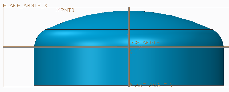
The point is on a surface through the center of the revolved surface. The surface can be hemispherical, ellipsoidal or torispherical. (it's a pressure vessel head).
Thanks!
Jeroen.
This thread is inactive and closed by the PTC Community Management Team. If you would like to provide a reply and re-open this thread, please notify the moderator and reference the thread. You may also use "Start a topic" button to ask a new question. Please be sure to include what version of the PTC product you are using so another community member knowledgeable about your version may be able to assist.
Solved! Go to Solution.
- Labels:
-
General
Accepted Solutions
- Mark as New
- Bookmark
- Subscribe
- Mute
- Subscribe to RSS Feed
- Permalink
- Notify Moderator
Hi Jeroen,
I think this will be a suitable solution for you.
Create a measure distance feature between the point and surface. This creates a datum point on the surface.
You can now create a curve through points and measure the angle.
See the attached file. I took the part from this discussion, copied the surfaces to a quilt and added the measure feature. I you correctly define the quilt it should be stable.
Patrick
- Mark as New
- Bookmark
- Subscribe
- Mute
- Subscribe to RSS Feed
- Permalink
- Notify Moderator
- Mark as New
- Bookmark
- Subscribe
- Mute
- Subscribe to RSS Feed
- Permalink
- Notify Moderator
- Mark as New
- Bookmark
- Subscribe
- Mute
- Subscribe to RSS Feed
- Permalink
- Notify Moderator
If i'm correct, your first example is not the one I'm looking for, the point is on the surface.
The second one seems to be exactly what I need.
But... If I try to replicate this, I cannot select both the point and the surface to (re)create this axis.
Can you help me out with this? How did you do this?
I'm a little bit closer now.
The point you created is defined as being on a distance normal to the surface.
By doing this, it is possible to 'revert' this action and draw an axis normal to this surface.
But...
The point I need to create is created with no reference to the surface.
It is on a datum plane (DTM3), and offsetted from DTM1 and DTM2.
Is it possible to create the normal axis like this?
- Mark as New
- Bookmark
- Subscribe
- Mute
- Subscribe to RSS Feed
- Permalink
- Notify Moderator
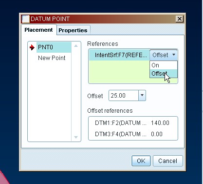
Hopefully the attached screen shot will explain, have you created the intent surface first? You also need to click the "on" to change it to "offset", (see screen shot).
John
- Mark as New
- Bookmark
- Subscribe
- Mute
- Subscribe to RSS Feed
- Permalink
- Notify Moderator
The problem I have is that the point is not referenced to the surface.
Hence, I cannot use the intentsurface as a reference for the point.
The point must have XYZ coordinates.
- Mark as New
- Bookmark
- Subscribe
- Mute
- Subscribe to RSS Feed
- Permalink
- Notify Moderator
Hi Jeroen,
ok, i just tried to re-create the part i gave you yesterday & also struggled, but i realise why. You need to create the datum point ON the surface to start with, then add the axis (picking the point first, then the surface). Then, redefine the point by changing the ON to OFFSET & regenerate. Hopefully, the axis will now normal to your surface. Why it won't allow allow you to pick the surface when the point is offset from the surface to start with, God only knows.
John
- Mark as New
- Bookmark
- Subscribe
- Mute
- Subscribe to RSS Feed
- Permalink
- Notify Moderator
I cannot get this to work the way i would like, but i came up this (see attached model)
John
- Mark as New
- Bookmark
- Subscribe
- Mute
- Subscribe to RSS Feed
- Permalink
- Notify Moderator
Jeroen,
I would try using a sketched entity since it is on a plane through the axis of the cylinder. Try this:
- go to sketcher in the plane of the axis and the point of interest.
- make the surface one of your references and the point another
- sketch a centerline tangent to the surface near where you expect the "axis" to be
- sketch a line or centerline through the point and perpendicular to the tangent line
- create a reference dimension to measure the angle of interest
Hope this helps,
Karl
- Mark as New
- Bookmark
- Subscribe
- Mute
- Subscribe to RSS Feed
- Permalink
- Notify Moderator
Hello,
I tried this, but the solution is not stable.
The surface is a pressure vessel head model. This model will be a master model that can vary in size and type (hemispherical, torispherical, ellipsiodal, ...) The sketch or other solution should be stable so it will regenerate in any possible situation.
- Mark as New
- Bookmark
- Subscribe
- Mute
- Subscribe to RSS Feed
- Permalink
- Notify Moderator
If the surface of the master model is created using a spline, the spline can be set to match any curvature within whatever accuracy you like and the solution will work.
- Mark as New
- Bookmark
- Subscribe
- Mute
- Subscribe to RSS Feed
- Permalink
- Notify Moderator
Hi Jeroen,
I think this will be a suitable solution for you.
Create a measure distance feature between the point and surface. This creates a datum point on the surface.
You can now create a curve through points and measure the angle.
See the attached file. I took the part from this discussion, copied the surfaces to a quilt and added the measure feature. I you correctly define the quilt it should be stable.
Patrick
- Mark as New
- Bookmark
- Subscribe
- Mute
- Subscribe to RSS Feed
- Permalink
- Notify Moderator
Nice one!
But strange, why would a measurement be able to find the normal projection, and why doesn't Creo allow this to do as a regular feature?
Nevertheless, thank you!
- Mark as New
- Bookmark
- Subscribe
- Mute
- Subscribe to RSS Feed
- Permalink
- Notify Moderator
It doesn't seem strange that the measurement would find the nearest point on a surface to a point in space, but it is strange that there isn't a more direct/obvious* way to do this.
It also works to create a sketch on a plane through the point and the tank's axis of revolution - a circle that is tangent to a reference curve of the profile of the surface, and centered on the point. Using a spline for the tank end driver offers unlimited flexibility in the shaping of the tank end, so there is no need to perform a geometry replacement. A second sketch can be created with a point that is constrained to being on both the circle and the curve, which is the tangency point, and a line drawn from that point through the original datum point to establish the angle.
The following seemed likely to work, but were not supported** in WF5:
Axis through a point, normal to a surface (expects 2 non-point offset references after the surface selection, maybe it works if another datum plane through the axis and the point is constructed.)
Project a point on a surface (only projects curves, though a degenerate case for a curve is a point ...)
Create a sketch with a reference line that is tangent to both the circle and the surface profile (since the circle is already tangent to the surface, this fails, but making the line tangent to only one picks some random location on either the curve or the circle and with it a random orientation)
Create a sketch with a point on both the circle and the reference curve, which is the point of tangency (fails as redundant constraint, but picking either the circle or reference curve alone leaves the point with an unrestricted degree of freedom and not at the tangency.)
*It's like a Zork knock-off where the phrases: Pick up the ball, lift the ball, get the ball, grab the ball, gather the ball, pack the ball, retrieve the ball, steal the ball, fetch the ball, harvest the ball, and obtain the ball, are all met with "I don't know how to ..." and it turns out the only acceptable answer is "Cradle the ball."
**Perhaps there is a secret handshake to get these to work, like click, shift-click, then ctrl-doubleclick.
- Mark as New
- Bookmark
- Subscribe
- Mute
- Subscribe to RSS Feed
- Permalink
- Notify Moderator
I found a secret handhake here in sketch-mode... ![]() (creo 2.0 M030)
(creo 2.0 M030)
In a sketch as described in your post, you can draw a circle tangent to the reference curve of the surface.
Then, completely separate form this circle, you draw a little line, first point on the reference curve, and tangent to this curve. (length not important).
Draw a second line starting from the same first point as the previous line, normal to that line. Length not important.
Now, add a coincident constraint between the second line and the center of the circle.
The second line will be tangent to the reference curve and the first point will also be on the circle.
It's "go to the ball" & "bend over" & "grab the ball" & "stand up" & "walk to me" & "hand over the ball" in stead of "bring me the ball" ![]()


