Community Tip - When posting, your subject should be specific and summarize your question. Here are some additional tips on asking a great question. X
- Community
- Creo+ and Creo Parametric
- 3D Part & Assembly Design
- Re: Editing import drawing data?
- Subscribe to RSS Feed
- Mark Topic as New
- Mark Topic as Read
- Float this Topic for Current User
- Bookmark
- Subscribe
- Mute
- Printer Friendly Page
Editing import drawing data?
- Mark as New
- Bookmark
- Subscribe
- Mute
- Subscribe to RSS Feed
- Permalink
- Notify Moderator
Editing import drawing data?
Hello;
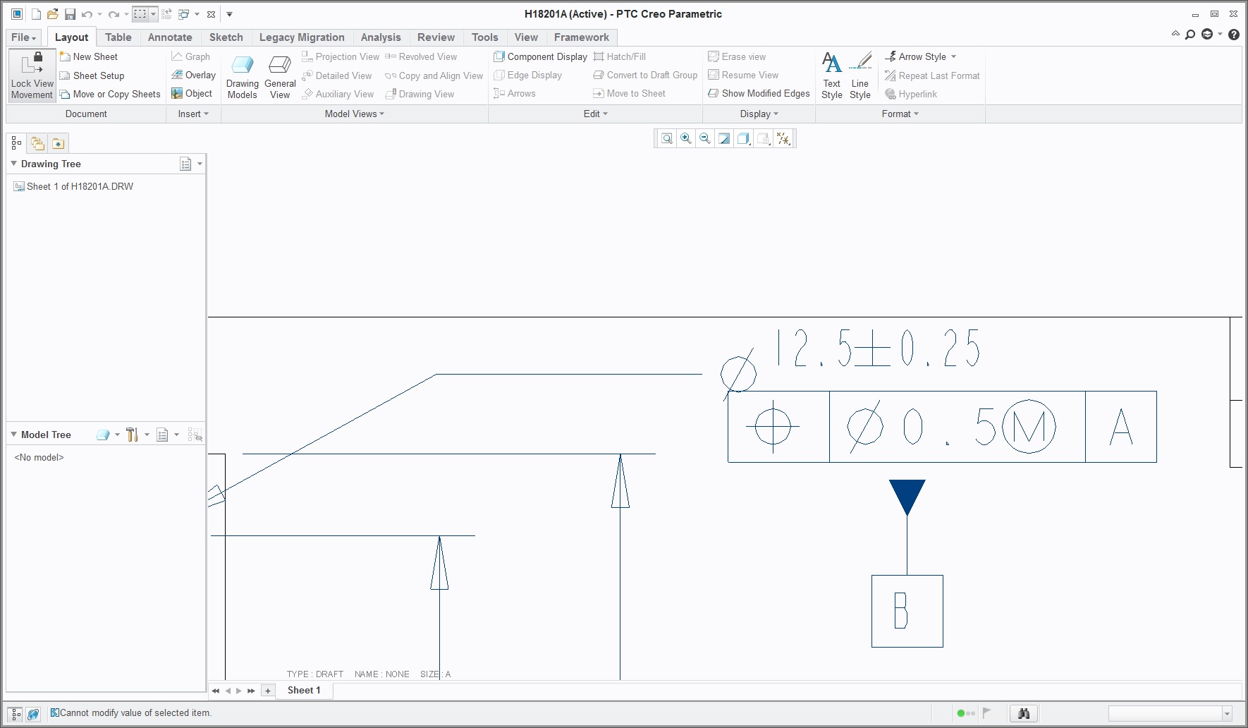
I have a bracket that has some dia. symbols with the callout, & for some reason it drops them down. I'm a SW user that needs CMG output so I have done a Creo drawing & inserted the dxf through the import drawing data. For some reason it drops the dia symbols down
& can't seem to edit them. Any way I can fix this?
Thanks in advance for any input.
Rob_D

- Labels:
-
2D Drawing
- Mark as New
- Bookmark
- Subscribe
- Mute
- Subscribe to RSS Feed
- Permalink
- Notify Moderator
This is very similar to Cannot figure out why when we plot our drawings our symbols show up below the text or at the bottom of the dimensions? Help...
I think you have a font issue...unfortunately the answer wasn't clear in the previous post. I assume you are using Creo 4.0
Matthew Ender, is there a work-around for this problem?
- Mark as New
- Bookmark
- Subscribe
- Mute
- Subscribe to RSS Feed
- Permalink
- Notify Moderator
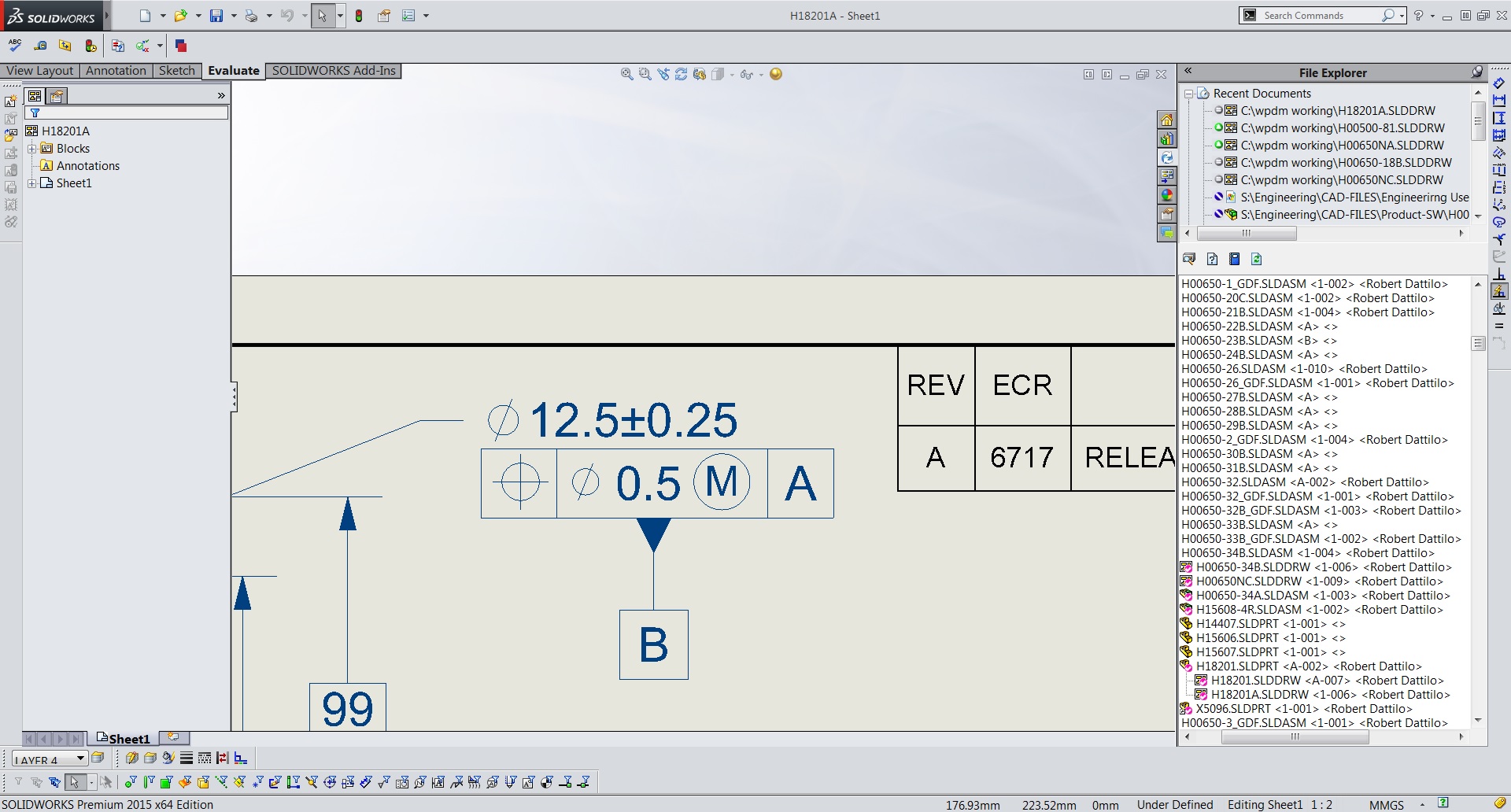
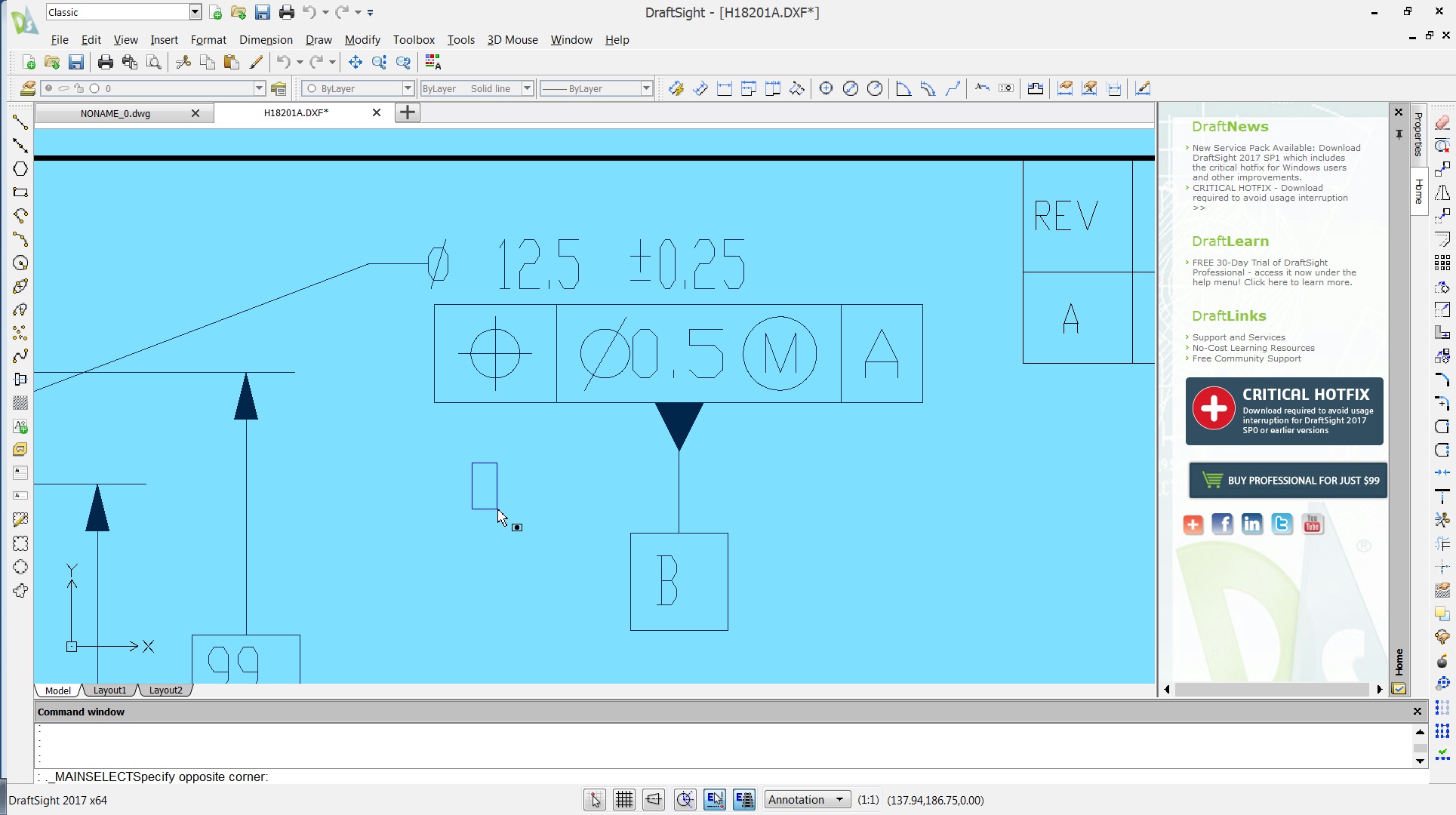
Sorry for any lack of clarity. A customer has requested CGM files, and I'm a Solidworks user & I can't create them from it, but can from Creo, which we have some licenses of etc. I create the dxf out of Solidworks, then use import drawing data in a Creo drawing, & everything is fine except it drops the dia. symbols. Here's my Solidworks file & Draftsight DXF.
Thanks for input;
Rob_D


- Mark as New
- Bookmark
- Subscribe
- Mute
- Subscribe to RSS Feed
- Permalink
- Notify Moderator
If you select the dimension and then right click properties, text style tab, what font does is say? Also, if you go to the annotate tab and select text style, then highlight over the dimension and the diameter symbol, do they highlight separately? (this is an indication they have different text styles)


- Mark as New
- Bookmark
- Subscribe
- Mute
- Subscribe to RSS Feed
- Permalink
- Notify Moderator
I don't have an SPR, so am working from the description. My analysis of 20-Apr is still my best guess here. If there were to be an SPR filed here (and its number noted in my direction) I could be sure.
- Mark as New
- Bookmark
- Subscribe
- Mute
- Subscribe to RSS Feed
- Permalink
- Notify Moderator
The diameter symbol is exactly where it should be. It is the dimension and Feature Control frame that are in the wrong place. You can see there is a font substitution between Solidworks and Creo.
You may have to fix it by hand because there won't be a common font and DXF doesn't know about Feature Control Frames and probably just draws it from lines and unrelated text. At least it should be consistently wrong. Even the Draftsight version fails to properly center the datum letter in the datum symbol.
The alternative is to find an independently created FCF font and force Solidworks to use that and then add that same font to the font list that Creo uses.
- Mark as New
- Bookmark
- Subscribe
- Mute
- Subscribe to RSS Feed
- Permalink
- Notify Moderator
Hi,
if you create and upload testing DXF file, I can test it in mu CR3 installation.
Use How to Attach a File to a Discussion Reply procedure.
MH
Martin Hanák


