Community Tip - Learn all about the Community Ranking System, a fun gamification element of the PTC Community. X
- Community
- Creo+ and Creo Parametric
- 3D Part & Assembly Design
- Embossing With an Image in Wildfire 5.0
- Subscribe to RSS Feed
- Mark Topic as New
- Mark Topic as Read
- Float this Topic for Current User
- Bookmark
- Subscribe
- Mute
- Printer Friendly Page
Embossing With an Image in Wildfire 5.0
- Mark as New
- Bookmark
- Subscribe
- Mute
- Subscribe to RSS Feed
- Permalink
- Notify Moderator
Embossing With an Image in Wildfire 5.0
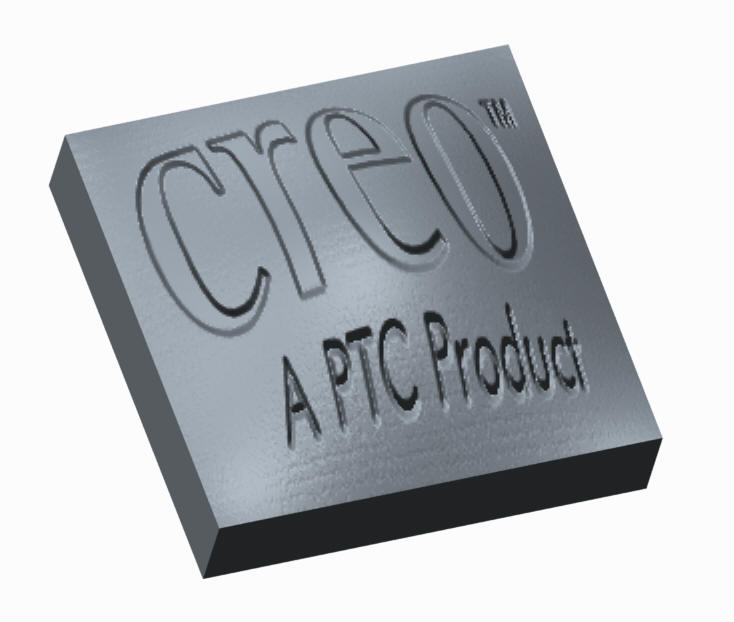
I am a college student and am currently using Pro/Engineer Wildfire 5.0, I have had a few courses in Pro/E but dont know many of the advanced functions of Pro/E. Anyways, I was wondering if there was a way to take an image file of a logo and use that image to emboss the logo on to the part creating indentation of the logo on the part.
Thanks for the help!
This thread is inactive and closed by the PTC Community Management Team. If you would like to provide a reply and re-open this thread, please notify the moderator and reference the thread. You may also use "Start a topic" button to ask a new question. Please be sure to include what version of the PTC product you are using so another community member knowledgeable about your version may be able to assist.
Solved! Go to Solution.
- Labels:
-
General
- Tags:
- emboss
- pro/engineer
Accepted Solutions
- Mark as New
- Bookmark
- Subscribe
- Mute
- Subscribe to RSS Feed
- Permalink
- Notify Moderator
I'm afraid that is not "the way" of Pro/E. But you do have two options: you can use the image as an underlay for a sketch so you can make an extrude feature, or with a few imaging tricks, you could make an image texture that would look like it was embossed when you do a rendering.
If you can get a DXF file (vector format file) of the logo that you can import, life gets much easier. A vector file can be converted to a sketch with relative ease.
- Mark as New
- Bookmark
- Subscribe
- Mute
- Subscribe to RSS Feed
- Permalink
- Notify Moderator
Ok, so if I i get a DXF file how do Import that, create the sketch, and place it on my part?
- Mark as New
- Bookmark
- Subscribe
- Mute
- Subscribe to RSS Feed
- Permalink
- Notify Moderator
I don't have WF5 so I cannot answer this directly. However, in Creo 2.0, when you select File>Open of a DXF file, it asks if you want to open it in sketcher or as a drawing. If you open it as a sketch, you can save it as a .sec file. Once you are in the part you want to use this sketch in, you can activate a sketch on the surface of the feature you want to emboss, and you can "get data" to import the sketch you saved earlier.
There are likely a few other ways, but that is all I can think of at the moment.
- Mark as New
- Bookmark
- Subscribe
- Mute
- Subscribe to RSS Feed
- Permalink
- Notify Moderator
Hi Clark,
this may not be possible in 'real 3D', in rendering however this is possible.
There you can use an black and white image wich is -using a bump map- then translated to surface offset information. This is only visual though and will not effect the model itself...

- Mark as New
- Bookmark
- Subscribe
- Mute
- Subscribe to RSS Feed
- Permalink
- Notify Moderator
Nice Constantin! Yes, a bump map was the second option I was leaning towards. The bump map is often overlooked as a rendering feature. It adds a lot of life and texture to a rendering.
- Mark as New
- Bookmark
- Subscribe
- Mute
- Subscribe to RSS Feed
- Permalink
- Notify Moderator
Can't comment on the exact commands as we're still in WF4, but you can import the .dxf into your model (you'll probably need to create a coordinate system to position it correctly, as there's no option to move or offset the import feature) and you can then just select it as a curve feature and Extrude it, IIRC.


