
Turn on suggestions
Auto-suggest helps you quickly narrow down your search results by suggesting possible matches as you type.
Showing results for
Please log in to access translation
Turn on suggestions
Auto-suggest helps you quickly narrow down your search results by suggesting possible matches as you type.
Showing results for
- Community
- Creo+ and Creo Parametric
- 3D Part & Assembly Design
- Re: Excessive displacement
Translate the entire conversation x
Please log in to access translation
Options
- Subscribe to RSS Feed
- Mark Topic as New
- Mark Topic as Read
- Float this Topic for Current User
- Bookmark
- Subscribe
- Mute
- Printer Friendly Page
Excessive displacement
May 24, 2017
03:46 AM
- Mark as New
- Bookmark
- Subscribe
- Mute
- Subscribe to RSS Feed
- Permalink
- Notify Moderator
Please log in to access translation
May 24, 2017
03:46 AM
Excessive displacement
Hello,
I have a simulation including a stationary body and a moving body. There is a contact between them. I often see the warning: "Excessive displacement at contact region". A software suggests smaller time step but I can not reduce it. The full moving process is described with 100 step and the software does not allow to define more...
1. What does it mean exactly the excessive displacement at the contact? Is the time step too large compared to distance between two mesh nodes? If I increase this distance (element size) - instead of time step reduction - is it correct?
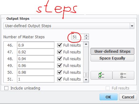
2. How can I define more steps under "User define output step"?
Thanks a lot your help;
Roland
Labels:
- Labels:
-
Data Exchange
28 REPLIES 28
May 25, 2017
10:15 AM
- Mark as New
- Bookmark
- Subscribe
- Mute
- Subscribe to RSS Feed
- Permalink
- Notify Moderator
Please log in to access translation
May 25, 2017
10:15 AM
1.Refine the elements of the contact region and have a try,sometimes it's hard to converge for the solver when the elements are too large.
2.Before it contacts each other,you can give less steps,then you have more steps for the contact steps.
3.You can only define less than 100 steps with a non-linear anaysis.
May 26, 2017
11:00 AM
- Mark as New
- Bookmark
- Subscribe
- Mute
- Subscribe to RSS Feed
- Permalink
- Notify Moderator
Please log in to access translation
May 26, 2017
11:00 AM
OK,thanks, I understand. My main problem is the "max 100 time steps". I have a quite long moving process and I should divide the full process to small steps but the 100 step possibility is not enough for me...
May 26, 2017
11:09 AM
- Mark as New
- Bookmark
- Subscribe
- Mute
- Subscribe to RSS Feed
- Permalink
- Notify Moderator
Please log in to access translation
May 26, 2017
11:09 AM
Roland,
i recommend: MSC MARC
creo simulate ist not possible in this case
regards
paul
May 26, 2017
09:12 PM
- Mark as New
- Bookmark
- Subscribe
- Mute
- Subscribe to RSS Feed
- Permalink
- Notify Moderator
Please log in to access translation
May 26, 2017
09:12 PM
Creo can do this large deformation analysis(below),so I think your question in not a problem.
May 27, 2017
02:41 AM
- Mark as New
- Bookmark
- Subscribe
- Mute
- Subscribe to RSS Feed
- Permalink
- Notify Moderator
Please log in to access translation
May 27, 2017
02:41 AM
Hi,
his problem is plasticity and contact and large deformation.
regards
paul
ps:
contact+large deformation: OK (example attached)
contact+plasticity: OK (example attached)
contact+plasticity+large deformation: not possible
May 29, 2017
02:57 AM
- Mark as New
- Bookmark
- Subscribe
- Mute
- Subscribe to RSS Feed
- Permalink
- Notify Moderator
Please log in to access translation
May 29, 2017
02:57 AM
My task is very similar to your 2. example (contact AND large deformation). But my model includes plasticity.
As far as I see, the main problem is that the time step has to be small because the parts are in contact continuosly. There is no a range during the motion process where the time step can be increased because the calculation will diverge in this range...
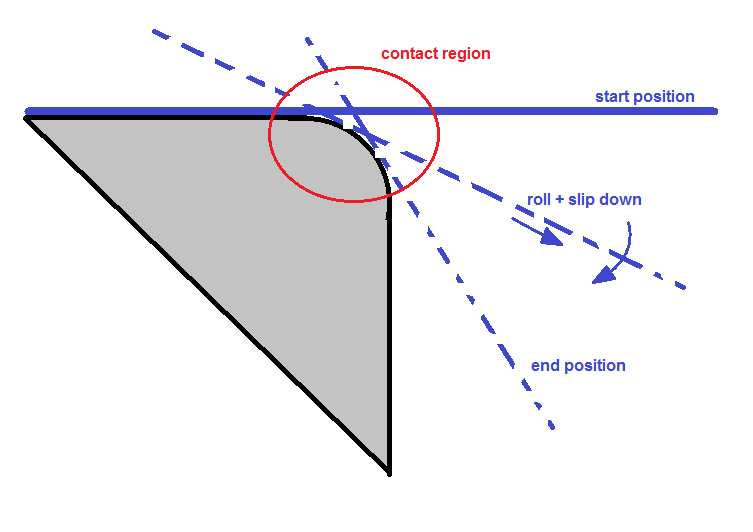
Second problem is that I has to calculate the backway of blue part. So my motion function (y in time):
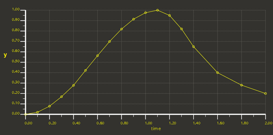
I would like ot investigate the final state, after the springback. If the time step is large after the maximal y then the contact will not be correct. Finally, I should divide this full timerange to 100 steps and it seems to me that it is inpossible with correct time step size...
May 29, 2017
06:59 AM
- Mark as New
- Bookmark
- Subscribe
- Mute
- Subscribe to RSS Feed
- Permalink
- Notify Moderator
Please log in to access translation
May 29, 2017
06:59 AM
Roland,
example as 3D (without plasticity):
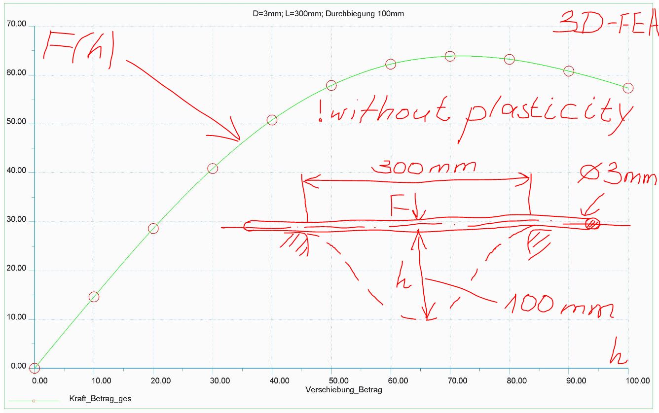
regards
paul
May 29, 2017
03:16 AM
- Mark as New
- Bookmark
- Subscribe
- Mute
- Subscribe to RSS Feed
- Permalink
- Notify Moderator
Please log in to access translation
May 29, 2017
03:16 AM
Paul wrote "contact+plasticity+large deformation: not possible"
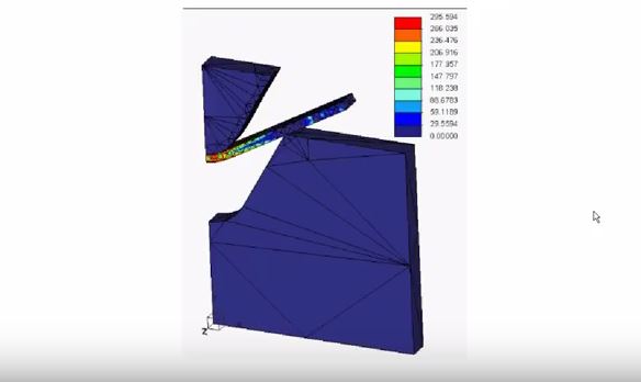
Here's picture from a problem I ran a few years ago, with contact, plasticity and large deformation.
You are restricted to using solid elements, I recall having tried 2D, but that did't work at the time, so I did a one element thick 3D analysis instead. If I remember correctly I did this in Creo 2 or 3.
May 29, 2017
03:42 AM
- Mark as New
- Bookmark
- Subscribe
- Mute
- Subscribe to RSS Feed
- Permalink
- Notify Moderator
Please log in to access translation
May 29, 2017
03:42 AM
Mats,
i mean 2d of course:

release: creo simulate 2.0 m080
regards
paul
Apr 05, 2024
04:56 PM
- Mark as New
- Bookmark
- Subscribe
- Mute
- Subscribe to RSS Feed
- Permalink
- Notify Moderator
Please log in to access translation
Apr 05, 2024
04:56 PM
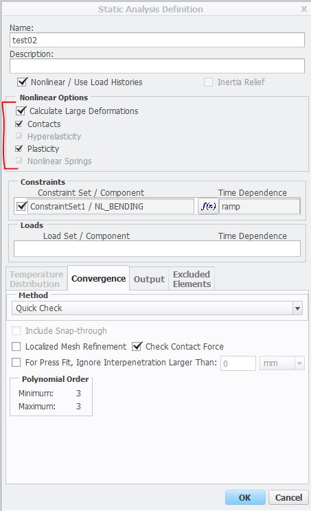
I have this message: "*** Warning: Large deformation and/or strain detected during contact analysis. More accurate results may be obtained if 'Calculate Large Deformations' is selected." while running FEA. But the button "Calculate Large Deformations" is gray as yours in this picture. So, not possible to select. What would you suggest to make the selection for "Calculate Large Deformations" available?
May 30, 2017
01:23 AM
- Mark as New
- Bookmark
- Subscribe
- Mute
- Subscribe to RSS Feed
- Permalink
- Notify Moderator
Please log in to access translation
May 30, 2017
01:23 AM
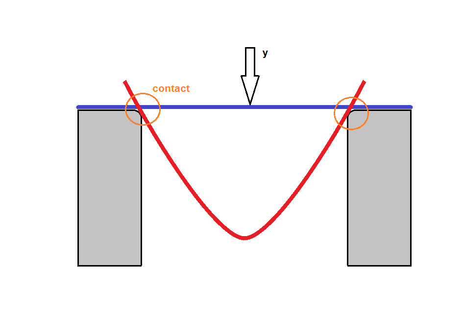
OK,
example attached (contact, large deformation and plasticity).
May 30, 2017
09:55 AM
- Mark as New
- Bookmark
- Subscribe
- Mute
- Subscribe to RSS Feed
- Permalink
- Notify Moderator
Please log in to access translation
May 30, 2017
09:55 AM
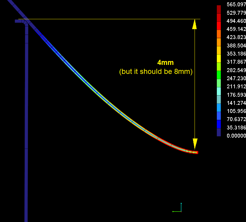
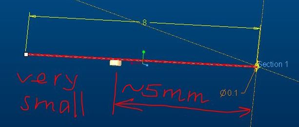
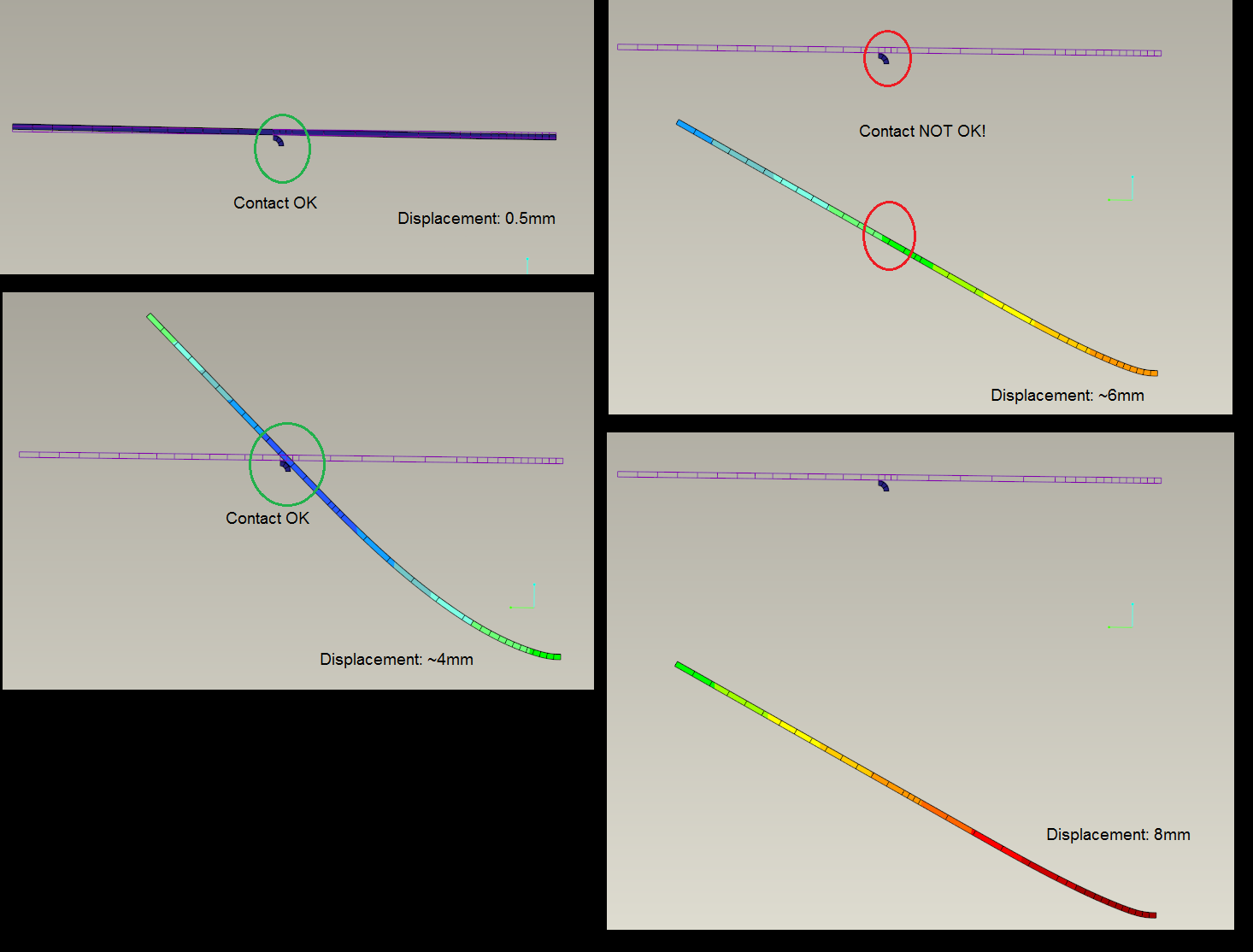
OK, it is a perfect example. My testcase includes plus 2 additional problems:
- the motion (down) is more higher so the plastic deformation is more larger too
- it should be modeled the backway of rod (to see the backspring) so I need additional time step but the 100 is not enough
The simulation is ok with 4mm displacement but the 8mm...
May 31, 2017
01:28 AM
- Mark as New
- Bookmark
- Subscribe
- Mute
- Subscribe to RSS Feed
- Permalink
- Notify Moderator
Please log in to access translation
May 31, 2017
01:28 AM
Hm,
i think it's a problem of force maybe:
better 2D-Analysis with MSC MARC
regards
paul
May 31, 2017
05:49 AM
- Mark as New
- Bookmark
- Subscribe
- Mute
- Subscribe to RSS Feed
- Permalink
- Notify Moderator
Please log in to access translation
May 31, 2017
07:02 AM
- Mark as New
- Bookmark
- Subscribe
- Mute
- Subscribe to RSS Feed
- Permalink
- Notify Moderator
Please log in to access translation
May 31, 2017
07:02 AM
I checked your model...the first observation; the mesh element number is similar to mine but the calculation time is total different. In your case about 2 minitt. In my case is about more hours.... Altough I use single pass adaptive...instead of quick check
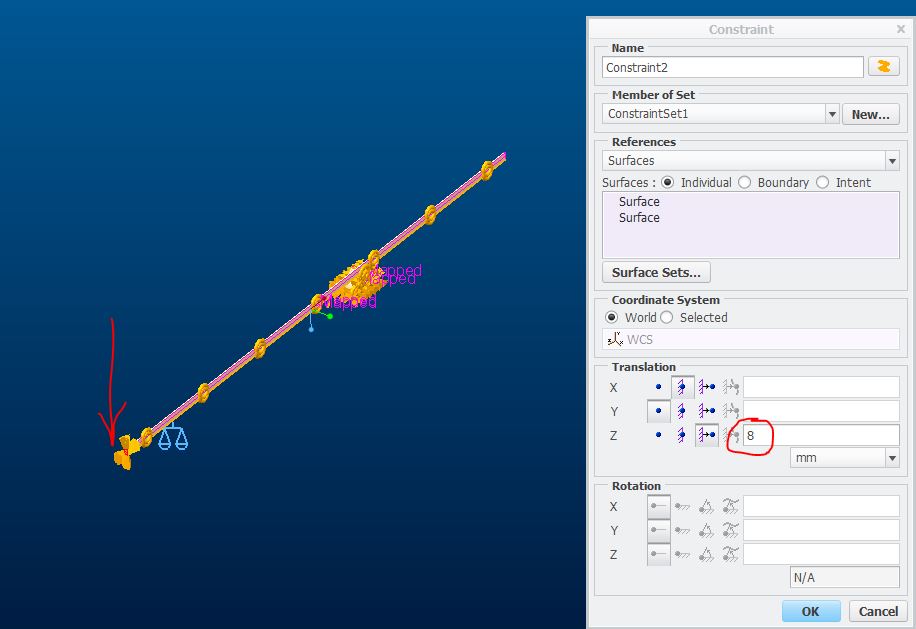
I control the motion by a displacement. (not with a force) As I mentioned, it should be investigate the backspring after maximal deflection. Therefore I can not control the end of rod as in your case. In this case the rod could not move free after maximal deflection.
My solution is unusual, I know but I control the support displacement. The support moves up 8mm and the end of rod is fixed as below:
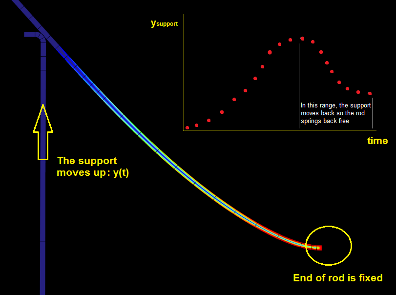
As a result, the rod can springs back free after maximal deflection. The reason of this solution, I would not like to use force control at the end of rod because the convergence is very slow with this way...
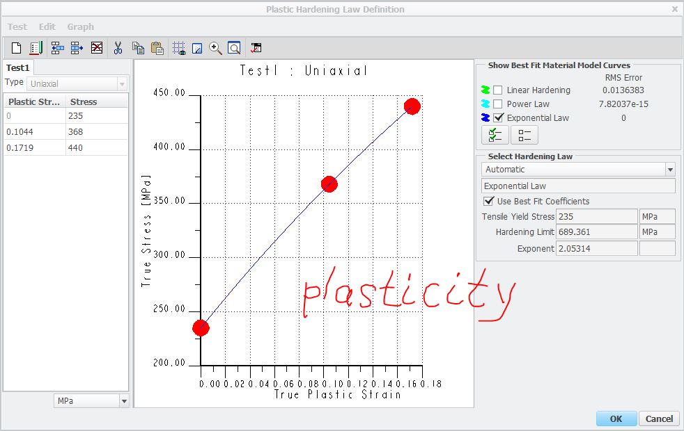
The other difference is the material model. My model is defined by power law but your model is a simple bilinear. Can the calculation be more slower caused by the non linear plastic renge of material model?
May 31, 2017
07:37 AM
- Mark as New
- Bookmark
- Subscribe
- Mute
- Subscribe to RSS Feed
- Permalink
- Notify Moderator
Please log in to access translation
Jun 01, 2017
04:06 AM
- Mark as New
- Bookmark
- Subscribe
- Mute
- Subscribe to RSS Feed
- Permalink
- Notify Moderator
Please log in to access translation
Jun 01, 2017
04:06 AM
Hello Paul,
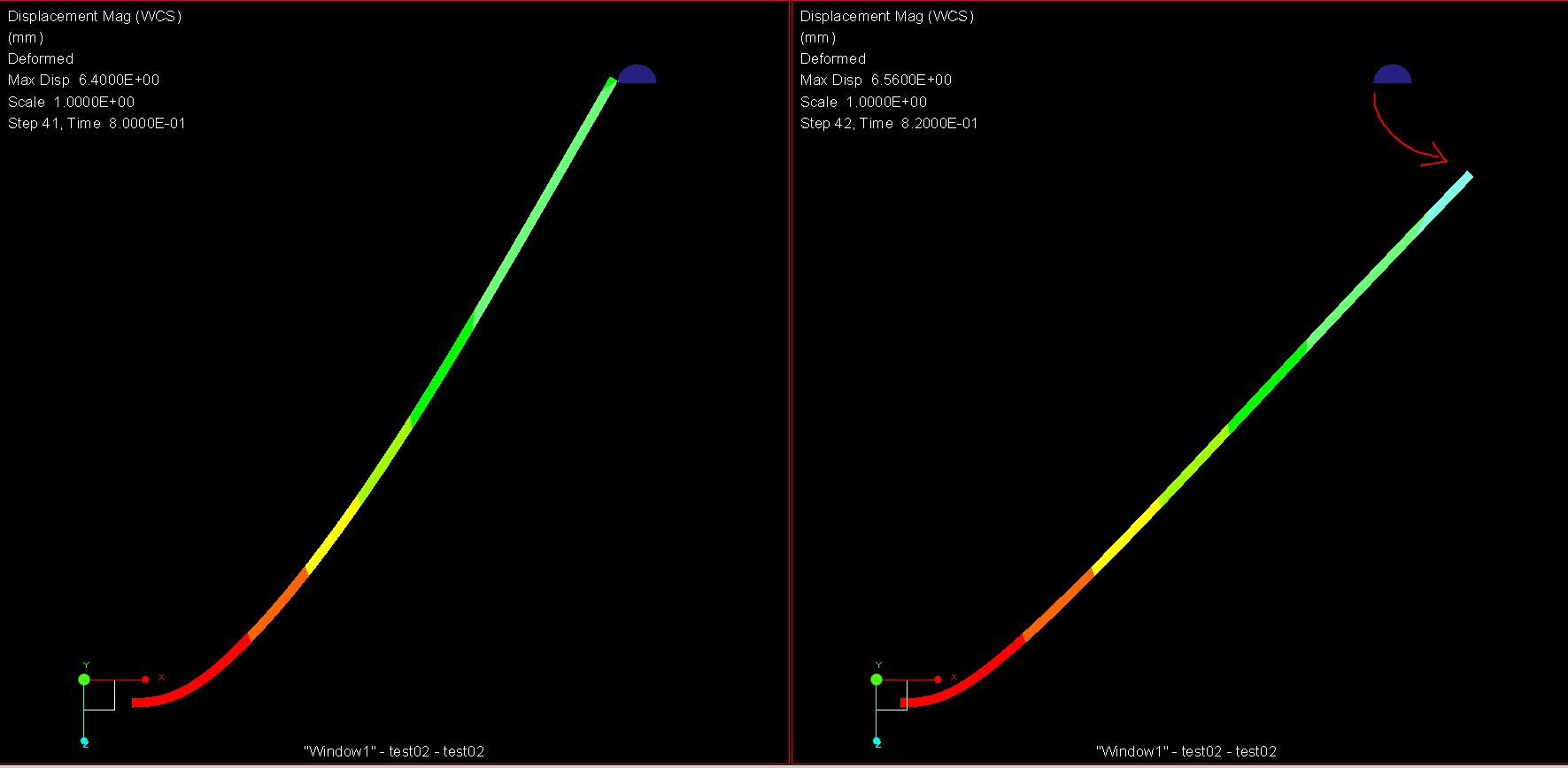
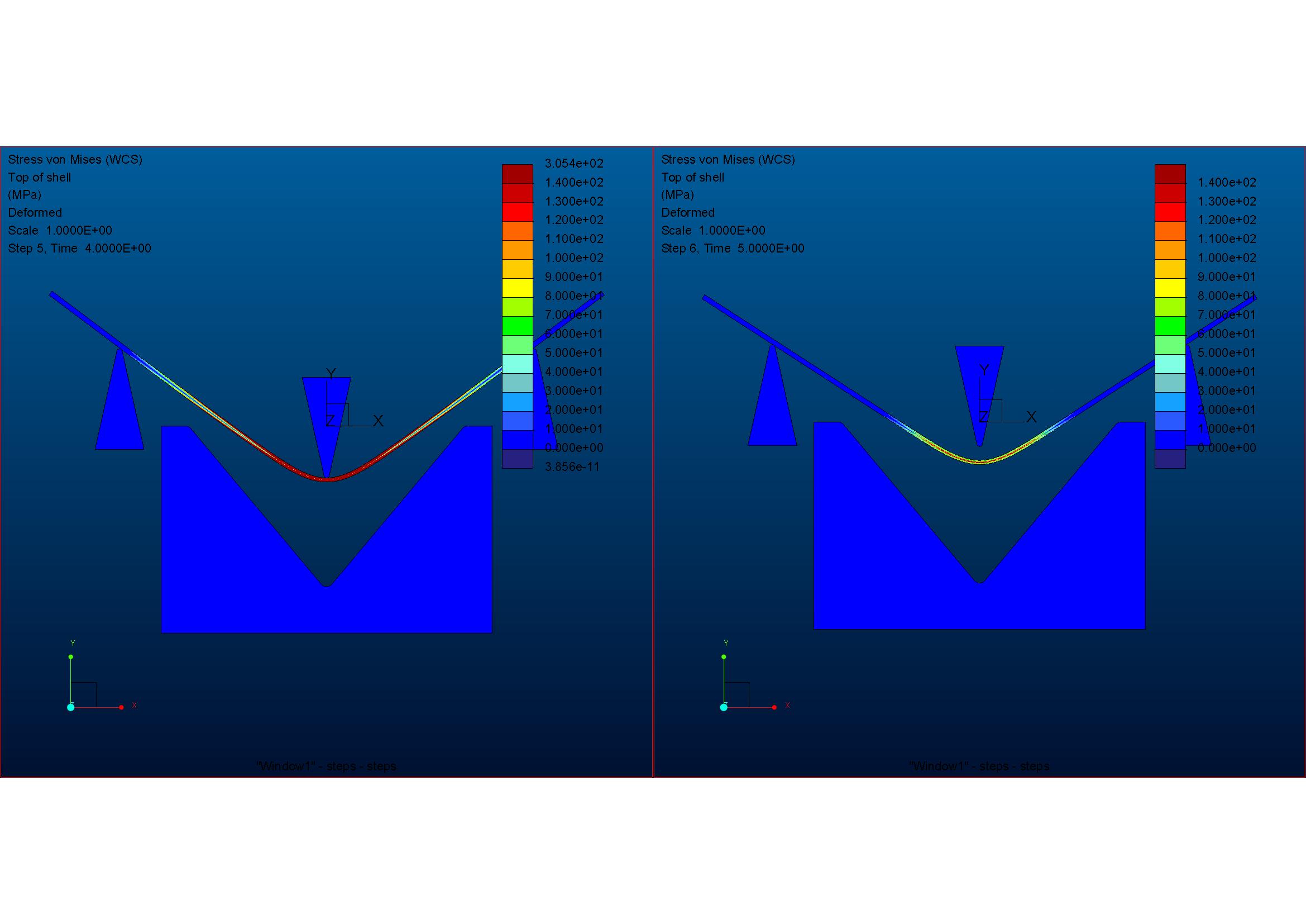
I dont understand what can cause the complexity of my model. See pls my result below:
After 6mm displacement, the contact lets loose the two parts....
I am using 100 time steps, total time is 1 s...I am not able to define smaller time step... Is this problem such complicated?
Jun 01, 2017
04:25 AM
- Mark as New
- Bookmark
- Subscribe
- Mute
- Subscribe to RSS Feed
- Permalink
- Notify Moderator
Please log in to access translation
Jun 01, 2017
04:25 AM
Hello Roland,
you can test my start-part and/or start-assembly (attached).
worked for mechanica specially
regards
paul
Jun 02, 2017
07:16 AM
- Mark as New
- Bookmark
- Subscribe
- Mute
- Subscribe to RSS Feed
- Permalink
- Notify Moderator
Please log in to access translation
Jun 02, 2017
07:16 AM
By the way, do you use the "Quick check" method always?
Jun 04, 2017
02:11 PM
- Mark as New
- Bookmark
- Subscribe
- Mute
- Subscribe to RSS Feed
- Permalink
- Notify Moderator
Please log in to access translation
Jun 04, 2017
02:11 PM
Jun 06, 2017
02:10 PM
- Mark as New
- Bookmark
- Subscribe
- Mute
- Subscribe to RSS Feed
- Permalink
- Notify Moderator
Please log in to access translation
Jun 06, 2017
02:10 PM
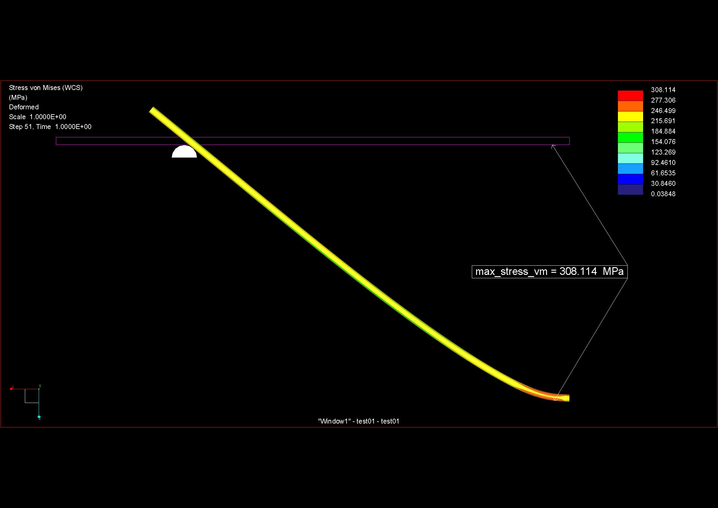
Roland,
I turned Paul's model 'upside down' to behave as yours so the cantilever constraint fixed and the semicircle support moves.
The semicircle support has 1mm enforced vertical movement and this enforced displacement is multiplied by a function.
The function has 200 steps (does not use the output tab at all) ...

A small animation showing permanent deformation

Tip displacement graph and final time step deformed plot

Model attached.
Regards
Jun 06, 2017
10:55 AM
- Mark as New
- Bookmark
- Subscribe
- Mute
- Subscribe to RSS Feed
- Permalink
- Notify Moderator
Please log in to access translation
Jun 06, 2017
10:55 AM
Paul,
I have asked this question before.
What's your opinion?
When do we use this (assuming the number of steps is less than 100) ?

When do we use this (other than for overcoming the '100 step' limit) ?

The functionality overlaps / is ambiguous. If you play around and inadvertently have both defined they fight each other with potential nonsense for output.
In both cases the steps do not have to be equal.
Using the 'time function' allows an import rather than typing.
Thanks
Charles
Jun 06, 2017
11:38 AM
- Mark as New
- Bookmark
- Subscribe
- Mute
- Subscribe to RSS Feed
- Permalink
- Notify Moderator
Please log in to access translation
Jun 06, 2017
11:38 AM
Also, using the 'function' we can unload gradually rather than in 1 big step
Jun 06, 2017
04:19 PM
- Mark as New
- Bookmark
- Subscribe
- Mute
- Subscribe to RSS Feed
- Permalink
- Notify Moderator
Please log in to access translation
Jun 06, 2017
04:19 PM
Charles,
more steps are more analysis, ongoing (example)
and full results pro step
regards
paul
Jun 07, 2017
08:28 AM
- Mark as New
- Bookmark
- Subscribe
- Mute
- Subscribe to RSS Feed
- Permalink
- Notify Moderator
Please log in to access translation
Jun 07, 2017
08:28 AM
Hello Charles,
wow, I didn't know this possibilities...it is very cool!
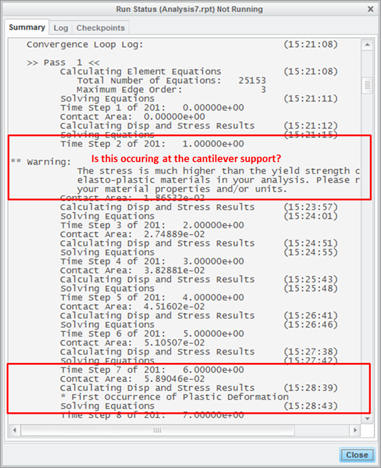
But tell me somebody, what is the cause the next warning:
"The stress is much higher than the yield strength of one of the
elasto-plastic materials in your analysis. Please review
your material properties and/or units."
I reduced the timestep size in the range where I see this warning, inspite of this, the convergence is not ok...moreover it diverged...
I investigated the result in the wrong time step. The stress is about 500 MPa, and the yield stress of material is 490 MPa. Why is the warning The stress is much higher than the yield strength? And why does the simulation diverge while the time step small, and the displacement/stress change slowly and gradually?
Jun 07, 2017
12:29 PM
- Mark as New
- Bookmark
- Subscribe
- Mute
- Subscribe to RSS Feed
- Permalink
- Notify Moderator
Please log in to access translation
Jun 07, 2017
12:29 PM
Roland,
My thoughts as follows (using Paul's model as reference) ...
The cantilever constraint creates a singularity. This cantilever constraint on the end surface is fully fixed and prevents poisson's effect. The circular edge all the way around the circumference at the cantilever support therefore will not be allowed to strain radially; something it wants to do naturally. This give a high stress. This stress is immediately much higher than the yield.
Therefore and despite a simple hand calculation showing a reasonable load is required before the outer fibre yields at the cantilever, the material in the corner yields straight away for any tiny movement of the semi-circular support. So it does not matter how small you make the time step.
A second thought is that stress at the contact is initially huge and settles down as the area increases. Again, I don't think reducing time steps helps. I make the material where contact is taking place linear. Use a volume region and apply linear properties to that. We can estimate the contact pressure by hand and in this case will be sensible but stresses at the contact are entirely dependent upon mesh quality.
There are other threads here with related discussion. These my raise more questions than answers though as your experience with 'diverging' solutions and time steps being continually cut is not new and is one reason why quick check is sometimes used rather than the full SPA ... some answers are better than nothing and potentially not the right thing to do. Of course, if the mesh is refined enough then element orders may be generally low enough that 3rd order is sufficient to adequately describe the solution.
More thoughts anyone??
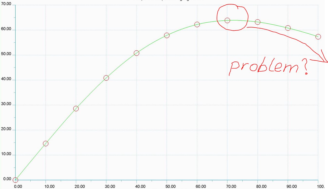
Mesh quality and quick check thoughts below ...
I know I should have the ordinate scales the same but it's not so easy to see the spikes in the measure response if I do.
The difference between answers for quick check and SPA with Paul's original mesh is very pronounced.
Tetra elements seem better. Refined mapped mesh SPA fails at the beginning of pass 2.


Jun 07, 2017
11:11 AM
- Mark as New
- Bookmark
- Subscribe
- Mute
- Subscribe to RSS Feed
- Permalink
- Notify Moderator
Please log in to access translation
Jun 07, 2017
11:11 AM
Paul,
I have been playing with your model to better understand the behaviour these creo functions.
Any thoughts on the following?
The support moves up; left end fixed as cantilever.
No movement = no stress - as expected
Any movement of the support bends the beam as a cantilever. Stresses should exist in the beam between the cantilever support and the semi-circular support.
We expect some interesting behaviour at the contact
Stresses cannot exist beyond the semi-circular support..
The following cannot be correct.

Jun 09, 2017
02:13 AM
- Mark as New
- Bookmark
- Subscribe
- Mute
- Subscribe to RSS Feed
- Permalink
- Notify Moderator
Please log in to access translation
Jun 09, 2017
02:13 AM
Hello Charles,
2d-analysis is maybe OK (bending_2d.zip as assembly attached):
but large deformation is not possible => better MSC MARC
regards
paul


