
Turn on suggestions
Auto-suggest helps you quickly narrow down your search results by suggesting possible matches as you type.
Showing results for
Please log in to access translation
Turn on suggestions
Auto-suggest helps you quickly narrow down your search results by suggesting possible matches as you type.
Showing results for
Community Tip - Your Friends List is a way to easily have access to the community members that you interact with the most! X
- Community
- Creo+ and Creo Parametric
- 3D Part & Assembly Design
- Explanations
Translate the entire conversation x
Please log in to access translation
Options
- Subscribe to RSS Feed
- Mark Topic as New
- Mark Topic as Read
- Float this Topic for Current User
- Bookmark
- Subscribe
- Mute
- Printer Friendly Page
Explanations
Apr 11, 2017
03:16 AM
- Mark as New
- Bookmark
- Subscribe
- Mute
- Subscribe to RSS Feed
- Permalink
- Notify Moderator
Please log in to access translation
Apr 11, 2017
03:16 AM
Explanations
Morning All
Can anybody help me or direct me to a resource for some of Creo's error messages? My current favourite is:
The boundary of the highlighted surfaces was extended. Unexpected results are possible.
I get this after merging two quilts yet when I search for single sided edges the quilts show gaps!
Labels:
- Labels:
-
General
- Tags:
- error messages
8 REPLIES 8
Apr 11, 2017
12:44 PM
- Mark as New
- Bookmark
- Subscribe
- Mute
- Subscribe to RSS Feed
- Permalink
- Notify Moderator
Please log in to access translation
Apr 11, 2017
12:44 PM
hi,
These error messages are mostly just recommendations, they can hardly describe what to do with the actual geometry. Do you mind attaching the model to a reply and specifying your version of Creo Parametric or Pro/E?
Apr 12, 2017
02:49 AM
- Mark as New
- Bookmark
- Subscribe
- Mute
- Subscribe to RSS Feed
- Permalink
- Notify Moderator
Please log in to access translation
Apr 12, 2017
02:49 AM
Hi James
After much fiddling and exploring the forum I have fixed the problem!
I changed the part accuracy to absolute and a value of 0.15, this is OK as the part is a large casting and does not require micron accuracy.
The accuracy was left as standard and was too fine. I just wish the cryptic messages were a little more helpful and PTC supplied a ready reckoner with useful pointers to fix the problems!
These forums are the best resource I've found.
Apr 12, 2017
12:17 PM
- Mark as New
- Bookmark
- Subscribe
- Mute
- Subscribe to RSS Feed
- Permalink
- Notify Moderator
Please log in to access translation
Apr 12, 2017
12:17 PM
hi Phil,
Ok, great, I guess you work on models with surfaces that are of organic or let's just say non-analytic shape. That's a pretty coarse accuracy you have there I'd say, even in millimeters. Too high or too low accuracy (depends on how you look at it) usually leads to a lot of trouble with these compound surfaces when the data have to be used in different CAD/CAM/CAE system afterwards. Think of a simple surface, like a cylinder, cone or even a sphere, analytic shapes like these can be converted to other CADs easily cause the other CAD can figure out the topology of the surface even when the accuracy is bad. Not so often with spherical shapes, but cylindrical and conical shapes transfer really well. The real trouble comes with models that have multiple supposedly merged non-analytic surfaces, in cases like these the resulting import to another CAD system happens to be with alot of gaps or even bad surfaces that need to be completely replaced. Such models require alot of effort to be fixed and solidified, effort which brings in no additional value. That's why setting up accuracy to this high number is usually not recommended.
Apr 13, 2017
02:32 AM
- Mark as New
- Bookmark
- Subscribe
- Mute
- Subscribe to RSS Feed
- Permalink
- Notify Moderator
Please log in to access translation
Apr 13, 2017
02:32 AM
Hi James
I had to make the accuracy coarse to make the model merge and solidify without errors.
This is what infuriates me, I have a common plane, on one side an extruded cylinder as a surface. On the other side it meets a sweep or boundary bend elbow.
No matter what I do to the geometry it has gaps and will not merge, the only cure is to change the part accuracy.
0.15 is fine for a rough old sand casting! 
Apr 17, 2017
04:18 PM
- Mark as New
- Bookmark
- Subscribe
- Mute
- Subscribe to RSS Feed
- Permalink
- Notify Moderator
Please log in to access translation
Apr 17, 2017
04:18 PM
That error comes from the boundaries of the two quilts not intersecting in an obvious way. Creo then has to make a guess as to how to terminate them, either by extending or trimming one or both quilts.
For example, look at these two quilts:
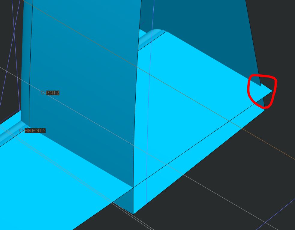
Where they cross (in the area circled) it's not obvious how they should be trimmed. If I merge them, Creo makes a guess:
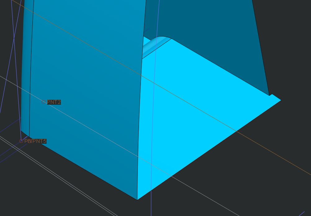
It trims the bottom quilt where it intersects the other, leaving a tail behind. Creo generates the error you mentioned, even though in this case it's more of a trim than an extend.
However, if I trim the bottom quilt first, to the plane where the other quilt is already trimmed:
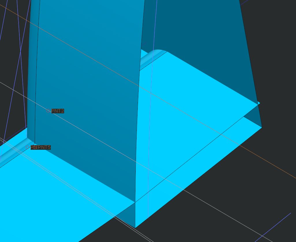
Then the merge is more obvious and is accomplished without error:
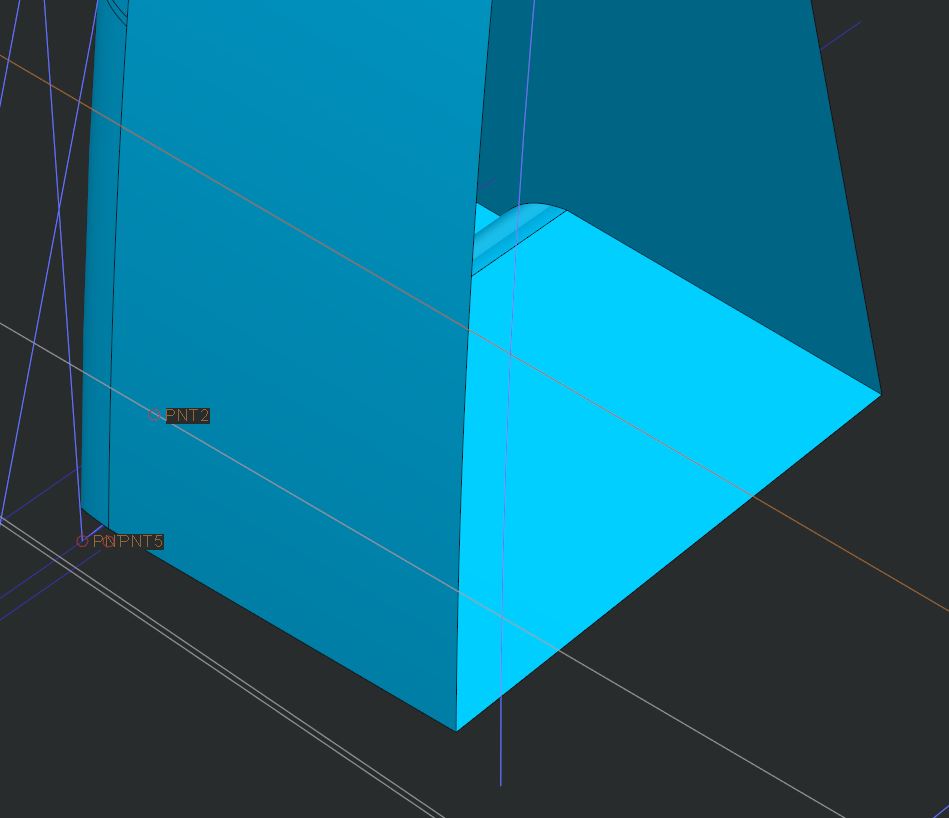
Can you post a screenshot of the intersection or better the model you are working with? We may be able to help you fix it.
Apr 18, 2017
02:35 AM
- Mark as New
- Bookmark
- Subscribe
- Mute
- Subscribe to RSS Feed
- Permalink
- Notify Moderator
Please log in to access translation
Apr 18, 2017
02:35 AM
Hi Doug
Thanks for the post, I have managed to fix the error by changing the part accuracy.
My beef is the way that a simple (to me!) interface on a common plane can produce errors. Where two parts meet Creo has produced gaps after a merge that then produce single edges that in turn prevent solidifying the whole part! 
If this a function of part accuracy then I have learned something! 
Apr 18, 2017
01:57 PM
- Mark as New
- Bookmark
- Subscribe
- Mute
- Subscribe to RSS Feed
- Permalink
- Notify Moderator
Please log in to access translation
Apr 18, 2017
01:57 PM
I don't think it is a function of accuracy, it's a function of how your surfaces intersect and the assumptions Creo makes when merging them. Changing accuracy changes the rules that govern the assumptions that Creo makes. In this case, it means the merge produces a closed quilt instead of an open one. It's masking the problem rather than correcting it. If it creates a good result for you then it may be a good fix. Keep in mind that it likely changed other parts of the model as well.
Absolute accuracy is a setting of the smallest allowed edge in the model. By setting it to 0.15mm (I assume you are using mm) Creo will resolve the model without creating any edges smaller than 0.15mm.
Apr 19, 2017
02:43 AM
- Mark as New
- Bookmark
- Subscribe
- Mute
- Subscribe to RSS Feed
- Permalink
- Notify Moderator
Please log in to access translation
Apr 19, 2017
02:43 AM
Hi Doug
I don't know the internal workings of Creo or how it interprets my geometry but my earlier post touched on how a simple geometry interface on a common plane can produce some many errors. Analysing the intersection shows gaps and I can't figure out why it has created them.
I spent some time playing with the accuracy figures, moving up and down the range to better understand it, and the effect is an eye opener.
By changing the absolute accuracy it has cured my problems, it is a single casting so no issues with other models.


