
Turn on suggestions
Auto-suggest helps you quickly narrow down your search results by suggesting possible matches as you type.
Showing results for
Please log in to access translation
Turn on suggestions
Auto-suggest helps you quickly narrow down your search results by suggesting possible matches as you type.
Showing results for
Community Tip - Need to share some code when posting a question or reply? Make sure to use the "Insert code sample" menu option. Learn more! X
- Community
- Creo+ and Creo Parametric
- 3D Part & Assembly Design
- Re: FEM on rubber disk
Translate the entire conversation x
Please log in to access translation
Options
- Subscribe to RSS Feed
- Mark Topic as New
- Mark Topic as Read
- Float this Topic for Current User
- Bookmark
- Subscribe
- Mute
- Printer Friendly Page
FEM on rubber disk
Aug 06, 2013
03:11 AM
- Mark as New
- Bookmark
- Subscribe
- Mute
- Subscribe to RSS Feed
- Permalink
- Notify Moderator
Please log in to access translation
Aug 06, 2013
03:11 AM
FEM on rubber disk
Hello everyone,
I am new to Creo simulation and met some problems as below:
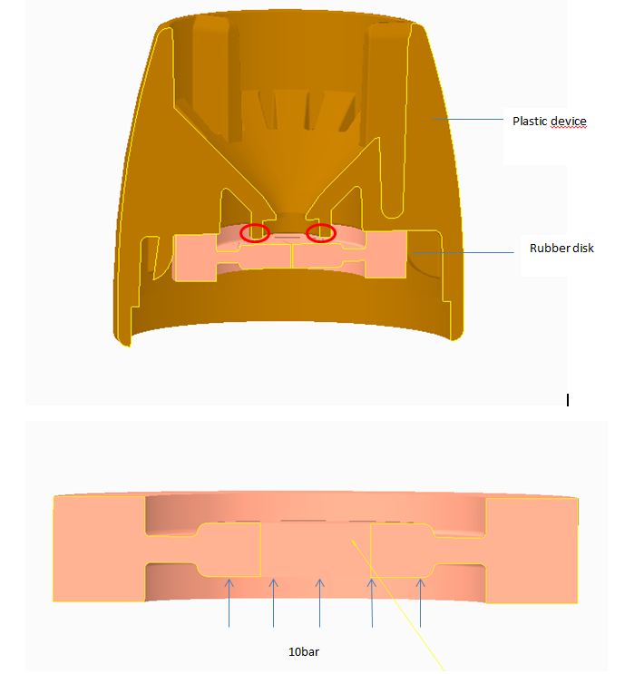
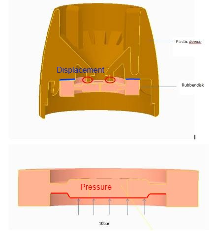
1. I wanna see how much deflection of rubber disk could be if providing 10 bar on the surface of inner ring. Rubber disk is equipped in the plastic device ( showed in the picture), so when it moves up, it will be blocked by the contact surface with the device( marked as the red circle), which means I need define the constrait on the contact surface, but I dont know how to do that. The top and bottom of outer ring are placed on the plastic part , so I give a constraint on them as well.
2. The rubber disk and plastic device as an assembly part, I am not sure if it is ok to do FEM on an assembly part.
3. The deformation of rubber disk compares to the dimension of rubber disk is small, so I considered it as linear situation, is that ok?
If anyone can help with these problems, I would appreciate that:)
This thread is inactive and closed by the PTC Community Management Team. If you would like to provide a reply and re-open this thread, please notify the moderator and reference the thread. You may also use "Start a topic" button to ask a new question. Please be sure to include what version of the PTC product you are using so another community member knowledgeable about your version may be able to assist.
Labels:
- Labels:
-
2D Drawing
13 REPLIES 13
Aug 06, 2013
07:59 AM
- Mark as New
- Bookmark
- Subscribe
- Mute
- Subscribe to RSS Feed
- Permalink
- Notify Moderator
Please log in to access translation
Aug 06, 2013
07:59 AM
Hello, Jo,
I do not have a clear answer yet,
I am attaching a link where there is an issue with rubber, I can help it.
Cordially.
Denis.
http://www.ptc.com/products/creo-elements-pro/wf4/localized/fr/tutorial_3272/printable_page.htm
Aug 06, 2013
09:50 AM
- Mark as New
- Bookmark
- Subscribe
- Mute
- Subscribe to RSS Feed
- Permalink
- Notify Moderator
Please log in to access translation
Aug 06, 2013
09:50 AM
Hi Denis,
Thanks for your help, it is very helpful for later analysis:)
But I still can not find a way to define the contace surface showed as red circle.
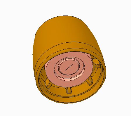
When I do simulation, I can not choose the contace surface cause it is as a whole part showed as below, what should I do?
Aug 06, 2013
09:58 AM
- Mark as New
- Bookmark
- Subscribe
- Mute
- Subscribe to RSS Feed
- Permalink
- Notify Moderator
Please log in to access translation
Aug 06, 2013
09:58 AM
Do you need to know what happens if the rubber disk contacts the plastic part?
Or do you only need to know whether it will contact?
If the latter, I think you can analyse just the rubber disk. I would use mirror symmetry in two directions to reduce the model size (and to help constrain it!), and then constrain the top surface only in the direction of the pressure.
I assume you know what the starting clearance is to the contact surface; you can therefore look at the maximum displacement value to decide whether the disk will contact under 10 bar.
Edited to add:
If you need to run it as an assembly* then you can select surfaces (and other entities) that you can't see by query-selecting, or (I think) tapping the right mouse button while highlighting your selection to cycle through other entities under the mouse pointer. It's sometimes useful to switch to hidden line or wireframe mode to do this.
*Note: a part is a single component, which has a single material and cannot be disassembled; an assembly contains one or more parts or other assemblies, which may have different materials; there is no such thing as an 'assembly part'.
Aug 08, 2013
05:17 AM
- Mark as New
- Bookmark
- Subscribe
- Mute
- Subscribe to RSS Feed
- Permalink
- Notify Moderator
Please log in to access translation
Aug 08, 2013
05:17 AM
Hi Jonathan,
Thanks for your reply:)
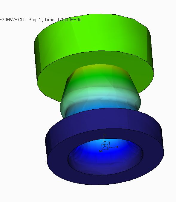
But I still have problem on that.I creat a new model to reduce the model size, which is on the plane 0.552mm above the inner ring of rubber disk. It is still in rubber disk.part .0.552mm is the clearance which is between the inner ring and the contact surface. Cause in one part, I cannot define the new model's material property.so even though I defined the concact interface, the contace surface still can not stop the rubber disk moving, it showes weried as below, what should I do next?
Aug 08, 2013
07:09 AM
- Mark as New
- Bookmark
- Subscribe
- Mute
- Subscribe to RSS Feed
- Permalink
- Notify Moderator
Please log in to access translation
Aug 08, 2013
07:09 AM
Is your new model an assembly? You need to use an assembly to analyse with contact.
As I said, I would use mirror symmetry in two directions, so analyse just a quarter of your model (you can create cuts in the assembly by solidifying two of the default planes). Then you can constrain the rubber disk using only the two symmetry constraints, and contacts with the other part - it will also make it easier to select the contacting surfaces.
Can you upload your parts?
Aug 08, 2013
08:27 AM
- Mark as New
- Bookmark
- Subscribe
- Mute
- Subscribe to RSS Feed
- Permalink
- Notify Moderator
Please log in to access translation
Aug 08, 2013
08:27 AM
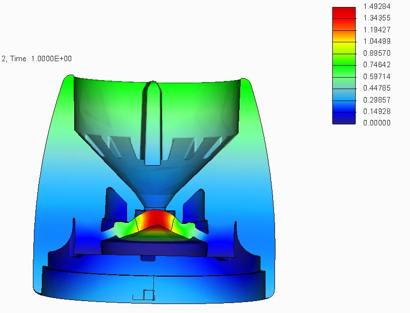
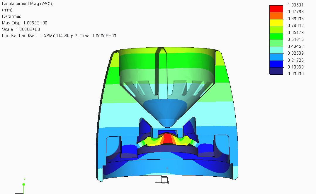
I tried again, as you said, first created cuts in the assembly by solidifying the plane, then constrained the bottom of outer ring of the rubber disk without displacement, providng 10 bars at the bottom surface of inner ring of rubber disk, defined the contact interface between the surface of inner ring and the conact surface of top of VTC. Simulation works, the result is showed as below, do you think all these processes are right? anything I missed?
Aug 08, 2013
08:38 AM
- Mark as New
- Bookmark
- Subscribe
- Mute
- Subscribe to RSS Feed
- Permalink
- Notify Moderator
Please log in to access translation
Aug 08, 2013
08:38 AM
- Why does your screenshot say "Time 1.0"? Have you run a linear static analysis, or something else?
- What deformation factor are your results displayed at? It looks like there is some interference between the two parts - it's possible you need to define more contact pairs*.
- What quantity is shown by the colour scale - displacement, or stress, or something else? What are the units? (I prefer not to show smoothed colours - they look nice, but I think the information is clearer with 'hard' contours.)
*If you are creating contact interfaces manually, you need to select every pair of surfaces that could contact. For example, if one part has surfaces A and B, and the other has X and Y, you may need to create:
A with X
A with Y
B with X
B with Y.
Aug 08, 2013
11:01 AM
- Mark as New
- Bookmark
- Subscribe
- Mute
- Subscribe to RSS Feed
- Permalink
- Notify Moderator
Please log in to access translation
Aug 08, 2013
11:01 AM
1. Time 1.0 is from the result window definition, I think that is set automatically. There are two steps, one is step 1 , time is 0s, and the other one is step 2, time is 1.0s. I ran a nonlinear analysis.
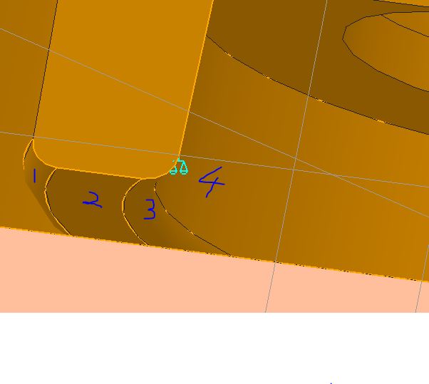
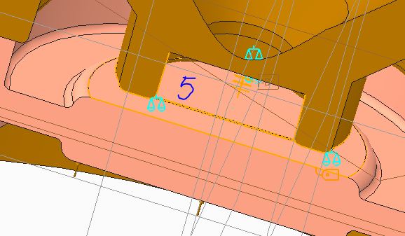
2. The doformation scale is 1. I defined 4 pairs of contace interface. surface 1 and 5, 2 and 5, 3 and 5, 4 and 5.
3.The simulation shows the displacement of rubber disk, unit is mm.
Is there still sth wrong?
Aug 09, 2013
03:35 AM
- Mark as New
- Bookmark
- Subscribe
- Mute
- Subscribe to RSS Feed
- Permalink
- Notify Moderator
Please log in to access translation
Aug 09, 2013
03:35 AM
It looks better in your latest results screenshot.
In the previous one, it looked as though the rubber disk was passing through surface 3, but I think you've fixed that now.
Aug 09, 2013
05:55 AM
- Mark as New
- Bookmark
- Subscribe
- Mute
- Subscribe to RSS Feed
- Permalink
- Notify Moderator
Please log in to access translation
Aug 09, 2013
05:55 AM
Thank you for answering me patiently and teaching me a lot:)
Aug 14, 2013
08:06 AM
- Mark as New
- Bookmark
- Subscribe
- Mute
- Subscribe to RSS Feed
- Permalink
- Notify Moderator
Please log in to access translation
Aug 14, 2013
08:06 AM
I am not sure if it comply with the design of your assembly, but I would have added a pressure load on the entire bottom surface of the disc and also constrained displacement of the top of the outer ring.
Did you choose "Calculate large deformations" in the nonlinear options?
Aug 08, 2013
11:49 AM
- Mark as New
- Bookmark
- Subscribe
- Mute
- Subscribe to RSS Feed
- Permalink
- Notify Moderator
Please log in to access translation
Aug 08, 2013
11:49 AM
Hello, Jo,
Have you tried the automatic detection of contact between the two parts.
What have you chosen as the material for your rubber?.
Cordially.
Denis.
http://www.qucosa.de/fileadmin/data/qucosa/documents/8714/SAXSIM_2012_Plasticity_Jakel.pdf
Aug 09, 2013
06:01 AM
- Mark as New
- Bookmark
- Subscribe
- Mute
- Subscribe to RSS Feed
- Permalink
- Notify Moderator
Please log in to access translation
Aug 09, 2013
06:01 AM
I tried the automatic detection of contact. It showed around 20 contact surfaces, and most of them seem no relevant. So I just chose 4 contact surfaces showed as above.
I defined a new material as silicon rubber and used it to the model.
Thanks for sharing the information on rubber disk:)


