
Turn on suggestions
Auto-suggest helps you quickly narrow down your search results by suggesting possible matches as you type.
Showing results for
Please log in to access translation
Turn on suggestions
Auto-suggest helps you quickly narrow down your search results by suggesting possible matches as you type.
Showing results for
Community Tip - Did you get an answer that solved your problem? Please mark it as an Accepted Solution so others with the same problem can find the answer easily. X
- Community
- Creo+ and Creo Parametric
- 3D Part & Assembly Design
- Re: Fill surface with guide curves
Translate the entire conversation x
Please log in to access translation
Options
- Subscribe to RSS Feed
- Mark Topic as New
- Mark Topic as Read
- Float this Topic for Current User
- Bookmark
- Subscribe
- Mute
- Printer Friendly Page
Fill surface with guide curves
Feb 27, 2013
01:07 PM
- Mark as New
- Bookmark
- Subscribe
- Mute
- Subscribe to RSS Feed
- Permalink
- Notify Moderator
Please log in to access translation
Feb 27, 2013
01:07 PM
Fill surface with guide curves
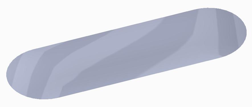
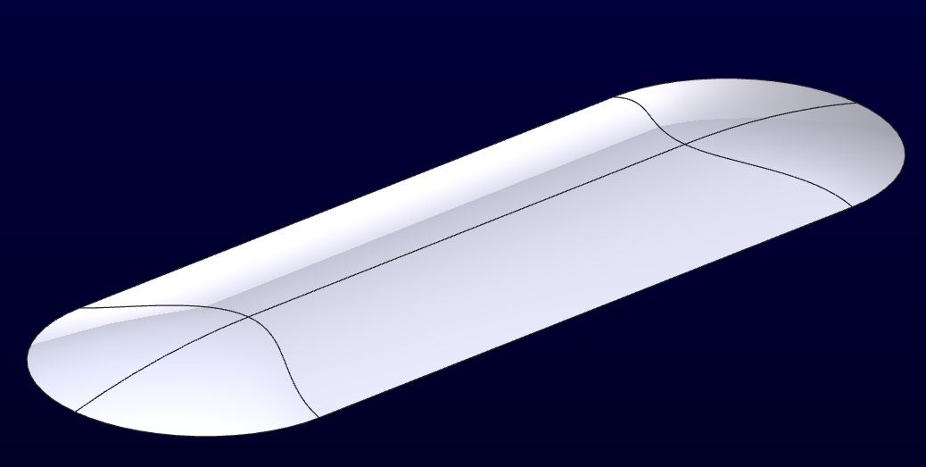
We are trying to create a surface that fills in a sketch and uses 2 curves to create a domed top. Can anyone tell me how to do it?
Here is a quick sketch of what we are trying to create. The 2 cross sketchs are raised.
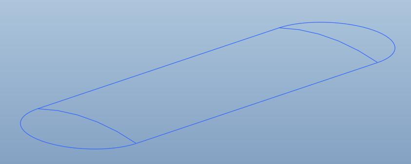
I have attached a model of this skeleton. I also attached a STEP file of what we are trying to end up with.
*** Note *** we need it to be a curvature continuous surface.
This thread is inactive and closed by the PTC Community Management Team. If you would like to provide a reply and re-open this thread, please notify the moderator and reference the thread. You may also use "Start a topic" button to ask a new question. Please be sure to include what version of the PTC product you are using so another community member knowledgeable about your version may be able to assist.
Solved! Go to Solution.
Labels:
- Labels:
-
Data Exchange
ACCEPTED SOLUTION
Accepted Solutions
Mar 01, 2013
11:32 AM
- Mark as New
- Bookmark
- Subscribe
- Mute
- Subscribe to RSS Feed
- Permalink
- Notify Moderator
Please log in to access translation
Mar 01, 2013
11:32 AM
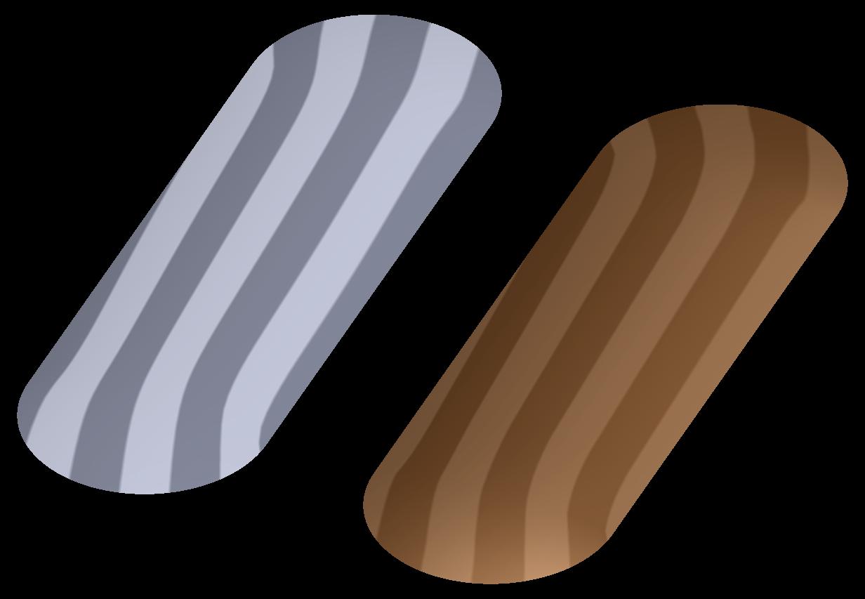
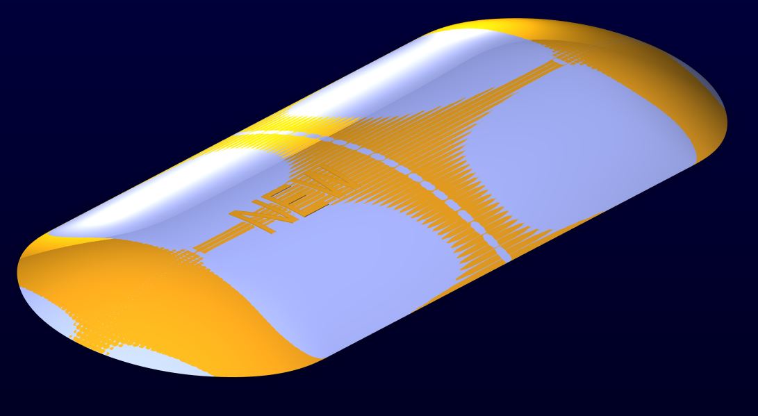
Ok, here's the latest and last stab at it. The surface is made with a VSS and with the exception of the spine, all the trajectory curves are conics with the rho vale for a perfect 90deg arc (use the sketcher section relation: rho = sqrt(2) - 1). If I used conics in the section of the VSS, it gave some funny artifacts at the curved edge, so the section was an arc driven by the 3 spines. I think this is a LITTLE better, but I think this is also the practical limit to Pro/E without the ISDX package. The grey surface is Pauls first STEP file, the bronze one is my latest. Have fun!
71 REPLIES 71
Feb 27, 2013
01:40 PM
- Mark as New
- Bookmark
- Subscribe
- Mute
- Subscribe to RSS Feed
- Permalink
- Notify Moderator
Please log in to access translation
Feb 27, 2013
01:40 PM
Very simple:
Extrude the arc on the right up to the arc on the left. Next, revolve 1/2 of the arc by creating a new sketch on the lft vertical plane, 180 degrees. Next, mirror that new endcap to the right side using the center plane. Next, select the center bit, and the the two ends (with CTRL) and click "merge"
Feb 27, 2013
01:44 PM
- Mark as New
- Bookmark
- Subscribe
- Mute
- Subscribe to RSS Feed
- Permalink
- Notify Moderator
Please log in to access translation
Feb 27, 2013
02:01 PM
- Mark as New
- Bookmark
- Subscribe
- Mute
- Subscribe to RSS Feed
- Permalink
- Notify Moderator
Please log in to access translation
Feb 27, 2013
02:01 PM
I tried that route but it creates a tangency at the points where the revolve meets the central extrude.
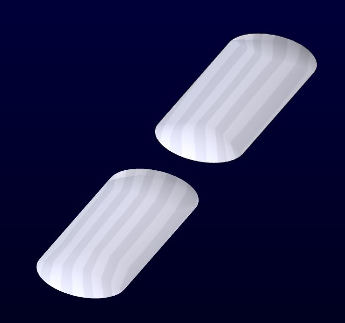
Here are some screenshots showing the reflection lines on the revolves compared to the STEP file.
Notice the much smoother reflection lines on the grey part below.
Industrial Design is requiring us to not have the tangency.
Feb 27, 2013
02:11 PM
- Mark as New
- Bookmark
- Subscribe
- Mute
- Subscribe to RSS Feed
- Permalink
- Notify Moderator
Please log in to access translation
Feb 27, 2013
02:11 PM
You didn't say that 
There must be some smoothing in the original that your sketch does not account for. This needs to be accounted for, obviously.
You might look up Tweak Tools... there are some tools that can take a planar surface and loft them based on guide curves. Specifically look at "section dome".
Feb 27, 2013
02:24 PM
- Mark as New
- Bookmark
- Subscribe
- Mute
- Subscribe to RSS Feed
- Permalink
- Notify Moderator
Please log in to access translation
Feb 27, 2013
02:24 PM
Looking at the Step file, the vertical section has a larger radius. In this case, you want to use some intelligent blend options along with control of the edge tangency. If you must duplicate the original exactly, you can use the Step file to obtain some of the critical information such as slopes and end angles. In essence, you have to figure out how the original was generated.
You can obtain curves from the original in one of several ways. I was building datums and creating sections. from the sections, you can generate datum curves "datums>Curve from Cross Section". The footprint can be projected from the surface to a plane.
Feb 27, 2013
02:34 PM
- Mark as New
- Bookmark
- Subscribe
- Mute
- Subscribe to RSS Feed
- Permalink
- Notify Moderator
Please log in to access translation
Feb 27, 2013
02:34 PM
Actually I did say it in the line that starts with ***Note*** 
I really appreciate your help.
The original was done in that other program by the ID guy. No smoothing just a Fill surface laid down and then the archs used as secondary curves.
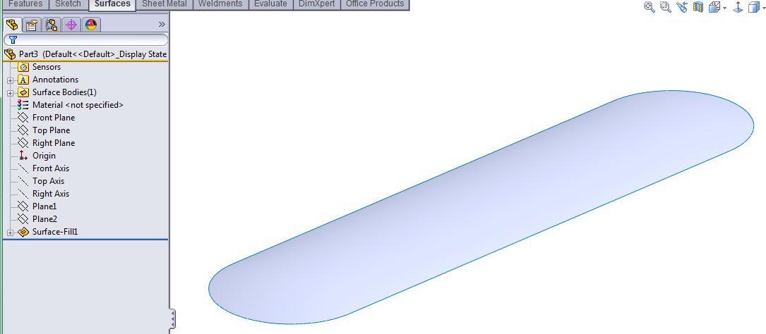
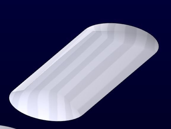
Here are some shots of the single feature created in SW. You start with the 3 sketches that I have in the skeleton. Then just lay a fill surface over them.
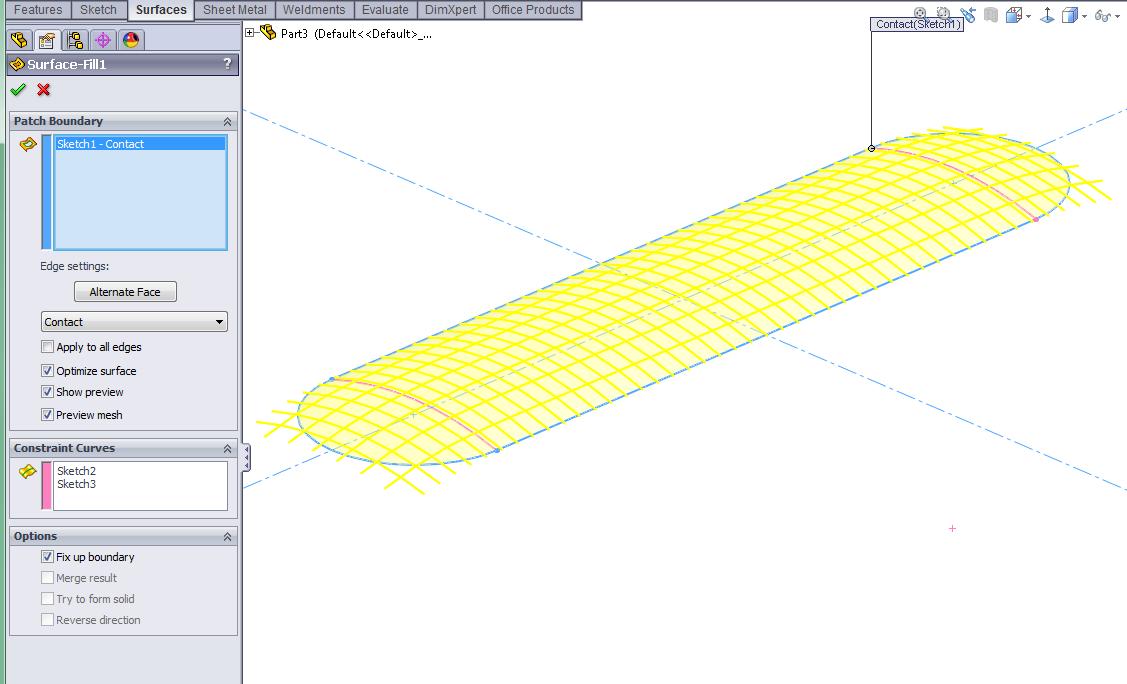
And you end up with this one feature. But the business group that is working on this project uses Creo so the editable design needs to be done in Creo.
Feb 27, 2013
02:55 PM
- Mark as New
- Bookmark
- Subscribe
- Mute
- Subscribe to RSS Feed
- Permalink
- Notify Moderator
Please log in to access translation
Feb 27, 2013
02:55 PM
Gotta love those ID guys... now I understand your ***note***.
You will see with careful scrutiny that the center of the import feature is actually depressed a slight amount (.1 in the STEP). There really is no straight element in the vertical section.
So the question remains... do they want "exactly" what they provided? Do they really want this 2-hump camel shape?
SolidWorks tends to make a lot of assumptions when creating features such as this. I have had the fortunate experience in doing exactly what you are trying to do here with SolidWorks. It really is a handful to manage. Creo can do this but certainly not as straight forward. You either allow assumptions with tweak features or you define every aspect.
Feb 27, 2013
03:33 PM
- Mark as New
- Bookmark
- Subscribe
- Mute
- Subscribe to RSS Feed
- Permalink
- Notify Moderator
Please log in to access translation
Feb 27, 2013
03:33 PM
In theory the center section would go straight across and not have the two humps in it. We originally thought we had it licked with the extrude/revolve trick, but the ID guy is stuck on the C2 idea for the top surface.
Getting the center flat can be done in SW by adding a 4th sketch between the two guide curves.
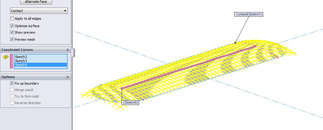
Attached are a copy of the SW file I am messing with and a step created from the SW file.
Feb 27, 2013
03:40 PM
- Mark as New
- Bookmark
- Subscribe
- Mute
- Subscribe to RSS Feed
- Permalink
- Notify Moderator
Please log in to access translation
Feb 27, 2013
03:40 PM
Now it is a very different part.
Feb 27, 2013
04:00 PM
- Mark as New
- Bookmark
- Subscribe
- Mute
- Subscribe to RSS Feed
- Permalink
- Notify Moderator
Please log in to access translation
Feb 27, 2013
04:00 PM
The "humps" are doing a lot for softening the transitions.
From a logical standpoint, I used the original profile to closely mimic the larger radius of the vertical section and came up with something that looked like this for surface transitions.
...which translates to this with the analysis:
which compares to the original step as:
I don't have the style module so I cannot go into this further. The tweak feature might give you something completely different.
Feb 27, 2013
04:07 PM
- Mark as New
- Bookmark
- Subscribe
- Mute
- Subscribe to RSS Feed
- Permalink
- Notify Moderator
Please log in to access translation
Feb 27, 2013
04:07 PM
Can you tell me how you created that or send me the file you created?
Feb 27, 2013
04:26 PM
- Mark as New
- Bookmark
- Subscribe
- Mute
- Subscribe to RSS Feed
- Permalink
- Notify Moderator
Please log in to access translation
Feb 27, 2013
04:26 PM
Its a bit messy, and a solid version using the obsolete "general blend" feature. A sweep blend should be able to do the same thing as general blend is archaic to understand. The real trick was obtaining the tangent faces which still have some optional definition opportunities.
If you taper the the two flat tangency faces, you can probably straighten the "S" transition along the target face.
Attached is Creo 2.0
PS: general blend created a solid (requires closed cross sections). It should be able to do this with surfaces as well.
Feb 27, 2013
04:48 PM
- Mark as New
- Bookmark
- Subscribe
- Mute
- Subscribe to RSS Feed
- Permalink
- Notify Moderator
Please log in to access translation
Feb 27, 2013
04:48 PM
That is really cool but the backbone sketch still has tangency in it, which causes tangency in the surface at the junction again.
Feb 27, 2013
04:59 PM
- Mark as New
- Bookmark
- Subscribe
- Mute
- Subscribe to RSS Feed
- Permalink
- Notify Moderator
Please log in to access translation
Feb 27, 2013
04:59 PM
How do you normally avoid that?
Feb 27, 2013
05:50 PM
- Mark as New
- Bookmark
- Subscribe
- Mute
- Subscribe to RSS Feed
- Permalink
- Notify Moderator
Please log in to access translation
Feb 27, 2013
05:50 PM
I don't know that is why I posted this. Creo doesn't seem to have a way of creating a C2 curve in a sketch without going to a spline, which is impossible to control.
Feb 27, 2013
08:20 PM
- Mark as New
- Bookmark
- Subscribe
- Mute
- Subscribe to RSS Feed
- Permalink
- Notify Moderator
Please log in to access translation
Feb 27, 2013
08:20 PM
Check out the 3:00 mark in this video:
http://www.youtube.com/watch?v=3fHUNnJ76b4
As for the spline, I am better able to control the splines today but in the longrun, they are simply a PITA to control. They seem to loose their definition on a whim.
Feb 27, 2013
06:38 PM
- Mark as New
- Bookmark
- Subscribe
- Mute
- Subscribe to RSS Feed
- Permalink
- Notify Moderator
Please log in to access translation
Feb 27, 2013
06:38 PM
Without what used to be called the ISDX surfacing module you can't really get C2 curvature. You can attempt it, but not quite get there. I'd tell your ID guy it's close enough unless he feels like doing it. The style guys want this and that, but unless you're doing high-speed airflow, or it's a reflector for a light, or it's the sheetmetal for a car, it's not reallya big hairy issue, he's just being too picky and Pro/E doesn't have the tools to 100% do it without that module. It's not the "tangency" that's the issue, it's that it's not C2 continuous curvature.
Here's a model I did with a couple different types of surfacing on it for ya.
Also.....why not just import the surfae where you want it, and do a solidify to add it to whatever solid geometry you have?
Feb 27, 2013
11:00 PM
- Mark as New
- Bookmark
- Subscribe
- Mute
- Subscribe to RSS Feed
- Permalink
- Notify Moderator
Please log in to access translation
Feb 27, 2013
11:00 PM
Sometimes Frank doesn't even know what kind of evil genius he really is...
Oh, did I say that out loud?
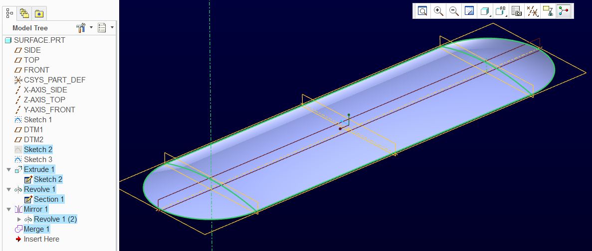
The Boundary Blend is probably the closest one can get without the Style extension. Notice that the command does have curvature options.
The attached was created with similar thoughts as the previous posts. When I tried to mirror only half the boundary blend, it had a really bad edge. Making the entire form in one go helped a lot.
You will find an ellipse in the flange face (for edge tangency) and you will find the "domes" controlled by a spline with an arc as a control feature. I am sure further refinement could be done with more boundary influence curves.
BTW: if you need to do this regularly, why don't you have the Style extension?
Feb 28, 2013
09:59 AM
- Mark as New
- Bookmark
- Subscribe
- Mute
- Subscribe to RSS Feed
- Permalink
- Notify Moderator
Please log in to access translation
Feb 28, 2013
09:59 AM
....insert Dr. Evil chuckle here......
I thought the VSS option was kind of interesting. Now I'm wondering if maybe using a conic section instead of an arc will smooth things out. Gonna try that.
I did the boundary blend with the curvature option (vs the tangency option if I remember) in the part I posted, and that still had the line that's so objectionable to the ID guy. I think in some instances a VSS gives you some options that the blend doesn't, and vice versa. I think the VSS opteion smoothed the transition out near the ends, but was obviously flattened (I emphasized it) in the middle. Although, I like that surface from a "styling" standpoint better than the ID guys! Looks cooler.
I'm going to try a conic and see where that gets me, and post that.
Did anyone have any luck opening the file I posted? I know some couldn't open things in the past.
The thing is, EXACTLY what surface do you want? The ID guys surface is NOT a cylindrical center with two fully radial ends, so what, exactly, is NEEDED (not neccessarily just wanted).
Feb 28, 2013
11:08 AM
- Mark as New
- Bookmark
- Subscribe
- Mute
- Subscribe to RSS Feed
- Permalink
- Notify Moderator
Please log in to access translation
Feb 28, 2013
11:08 AM
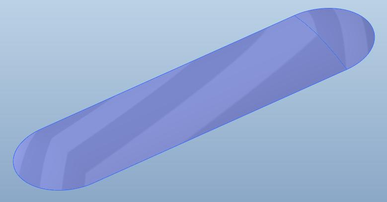
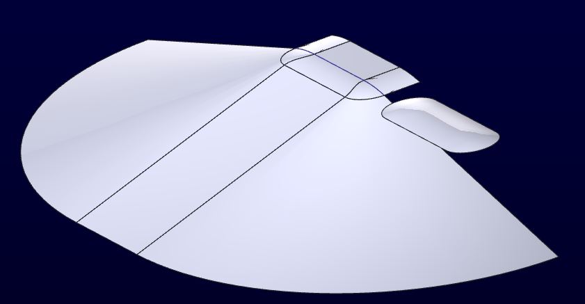
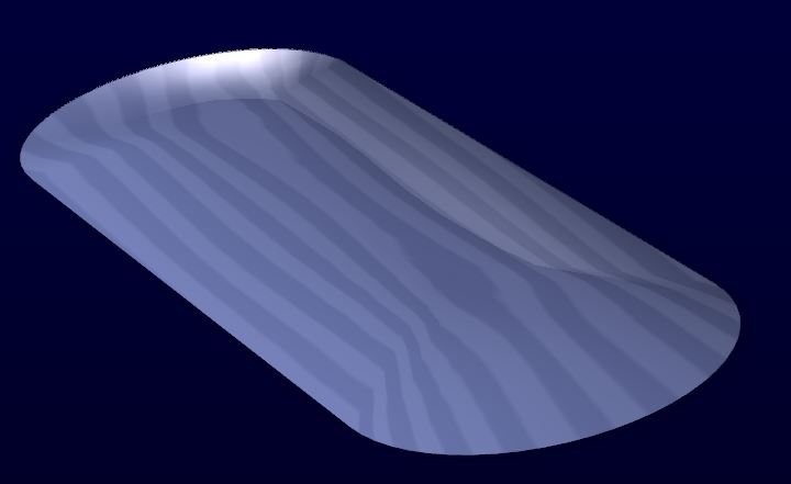
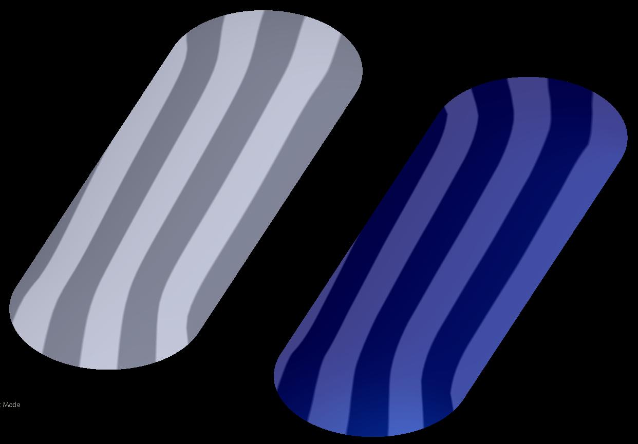
Ok, so, I think using a conic is a way of cheating, and getting as close to a C2 as you can. You need to make sure the conic's tangency's at the ends are correct (see model). Here's a pic, and I've attached the model. The grey surface is the STEP file Paul attached, the blue one is mine with the VSS using a curve that had a conic in it for one of the trajectories. I tried conics in the section, but it didn't work out as well as a simple arc. Have fun!
Feb 28, 2013
11:17 AM
- Mark as New
- Bookmark
- Subscribe
- Mute
- Subscribe to RSS Feed
- Permalink
- Notify Moderator
Please log in to access translation
Feb 28, 2013
11:17 AM
That one looks really good. I will see what they think.
Feb 28, 2013
01:40 PM
- Mark as New
- Bookmark
- Subscribe
- Mute
- Subscribe to RSS Feed
- Permalink
- Notify Moderator
Please log in to access translation
Feb 28, 2013
01:40 PM
Frank, is the VSS an ISDX feature? I cannot seem to duplicate this in core Creo using the basic Sweep feature. Your tangency tab is blanked and mine won't follow the edges. Everything else looks the same.
Feb 28, 2013
01:59 PM
- Mark as New
- Bookmark
- Subscribe
- Mute
- Subscribe to RSS Feed
- Permalink
- Notify Moderator
Please log in to access translation
Feb 28, 2013
01:59 PM
Shouldn't be, VSS's (Variable Section Sweeps) have been around forever. I'm on WF5/creo, maybe it's different if you're on creo 2?
To get the section to change during the VSS, you MUST make sure the section entities/vertexes you want to change are aligned to the reference (not construction) points you want, corresponding to the starting points of the trajectories.
Were you by chance trying a swept blend or regular sweep instead of a VSS?
Feb 28, 2013
02:44 PM
- Mark as New
- Bookmark
- Subscribe
- Mute
- Subscribe to RSS Feed
- Permalink
- Notify Moderator
Please log in to access translation
Feb 28, 2013
02:44 PM
I love the way these discussions seem like voyages to discovery 
Frank, your VSS translates to a normal sweep in Creo. It works correctly in your model, but I cannot duplicate it in mine, not verbatim. I did get it to work however by using the spine as a trajectory and the two side curves as guides. I also found the VSS tutorial on the knowledgebase so supposedly, the sweet has replaced the VSS although it is not the same. We can discuss more later. I will try to make a tutorial for discussion later.
Paul, I got very close to the original. The light acts very close to the original and so do the iso reflections.
They are -not- the same although I used 3/4 references from the original. I copies the spine, the "floor" and the section at the center. I swept the center section along 1/2 the spine and used the "floor" as guide curves.
The overlay looks something like this:
Feb 28, 2013
02:51 PM
- Mark as New
- Bookmark
- Subscribe
- Mute
- Subscribe to RSS Feed
- Permalink
- Notify Moderator
Please log in to access translation
Feb 28, 2013
03:43 PM
- Mark as New
- Bookmark
- Subscribe
- Mute
- Subscribe to RSS Feed
- Permalink
- Notify Moderator
Please log in to access translation
Feb 28, 2013
03:43 PM
Hey Antonius. Hmmm, is it me or is Pro/E just getting worse?
VSS's are extremely powerful tools, and I'm appalled they're no longer supported. It doesn't sound like the "sweep" tool is an enhancement, especially if it can't reproduce what a VSS can. With the VSS, I used a spine, and 3 additional curves to get the shape: The side curves, and the top curve (containing the conic) which seems to blend the surfaces better. You weren't able to use the top curve above the spine? What a total crock. The more I hear this, the more I just want to go back to WF4 permanently. I just did this in creo because I was already in it.. How is taking away features that USED to work awesome, an "enhancement"?
You're on creo parametric, right? Or is it called creo 2 now?
With a CAD system like Pro/E, my overwhelming need is the ability to create complex geometry, even drawings are of secondary importance. sounds like, again, they have TOTALLY dropped the ball.
Feb 28, 2013
04:46 PM
- Mark as New
- Bookmark
- Subscribe
- Mute
- Subscribe to RSS Feed
- Permalink
- Notify Moderator
Please log in to access translation
Feb 28, 2013
04:46 PM
Yep, I'm in Creo 2 also known as Creo Elements | Pro.
I could not use the straight line as a trajectory (original) and it would not follow the spine no matter what I did.
I still have to go through the tutorial I found to see if it works. It is the tutorial of the bottle.
I will let you know how that turns out.
One thing, however, the file you posted is "fragile" in Creo 2.0. The second VSS sweep gets an error out of the blue. Sketches are simply not maintaining relevant references. They certainly don't self-heal in regeneration. Very poor performance all together.
Feb 28, 2013
04:59 PM
- Mark as New
- Bookmark
- Subscribe
- Mute
- Subscribe to RSS Feed
- Permalink
- Notify Moderator
Please log in to access translation
Feb 28, 2013
04:59 PM
I'm in Creo 2 also known as Creo Elements | Pro.
Actually, 'Creo Elements | Pro' is not the same as Creo 2.0, it's 2 releases prior. Pro/E WF5 and Creo Elements | Pro are the same release, then came Creo 1.0 and then Creo 2.0.
Lots of folks get confused by that. I wish PTC had left WF5 alone and not re-branded it Creo Elements | Pro.
Creo Parametric is one of several Creo 'apps' in the Creo suite. The current release of Creo is 2.0. In addition to Parametric (which we knew as Pro/E), there is Creo Direct (a 'direct modeler' like CoCreate, but it isn't a CoCreate replacement), Creo View (formerly 'ProductView) and Creo Sketch, a free simple 2D drawing program.
Feb 28, 2013
05:14 PM
- Mark as New
- Bookmark
- Subscribe
- Mute
- Subscribe to RSS Feed
- Permalink
- Notify Moderator
Please log in to access translation
Feb 28, 2013
05:14 PM
Thanks for the clarification, Doug. I know it was a nightmare to figure out last year when I was looking at what I needed.


