
Turn on suggestions
Auto-suggest helps you quickly narrow down your search results by suggesting possible matches as you type.
Showing results for
Please log in to access translation
Turn on suggestions
Auto-suggest helps you quickly narrow down your search results by suggesting possible matches as you type.
Showing results for
Community Tip - Have a PTC product question you need answered fast? Chances are someone has asked it before. Learn about the community search. X
- Community
- Creo+ and Creo Parametric
- 3D Part & Assembly Design
- Re: Fill surface with guide curves
Translate the entire conversation x
Please log in to access translation
Options
- Subscribe to RSS Feed
- Mark Topic as New
- Mark Topic as Read
- Float this Topic for Current User
- Bookmark
- Subscribe
- Mute
- Printer Friendly Page
Fill surface with guide curves
Feb 27, 2013
01:07 PM
- Mark as New
- Bookmark
- Subscribe
- Mute
- Subscribe to RSS Feed
- Permalink
- Notify Moderator
Please log in to access translation
Feb 27, 2013
01:07 PM
Fill surface with guide curves
We are trying to create a surface that fills in a sketch and uses 2 curves to create a domed top. Can anyone tell me how to do it?
Here is a quick sketch of what we are trying to create. The 2 cross sketchs are raised.
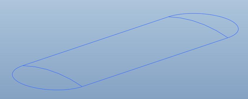
I have attached a model of this skeleton. I also attached a STEP file of what we are trying to end up with.
*** Note *** we need it to be a curvature continuous surface.
This thread is inactive and closed by the PTC Community Management Team. If you would like to provide a reply and re-open this thread, please notify the moderator and reference the thread. You may also use "Start a topic" button to ask a new question. Please be sure to include what version of the PTC product you are using so another community member knowledgeable about your version may be able to assist.
Solved! Go to Solution.
Labels:
- Labels:
-
Data Exchange
71 REPLIES 71
Feb 28, 2013
05:06 PM
- Mark as New
- Bookmark
- Subscribe
- Mute
- Subscribe to RSS Feed
- Permalink
- Notify Moderator
Please log in to access translation
Feb 28, 2013
05:06 PM
Wonderful. Way to keep "continuity" (sorry!  ) PTC........ Too bad, because the second VSS is the one that works best.
Can you go back a couple versions and look at it? I use VSS's for a TON of stuff, because they work so well, and if it no longer works that's going to be a REAL issue.
Wow, it just keeps getting even worse doesn't it?
Feb 28, 2013
05:21 PM
- Mark as New
- Bookmark
- Subscribe
- Mute
- Subscribe to RSS Feed
- Permalink
- Notify Moderator
Please log in to access translation
Feb 28, 2013
05:21 PM
The tutorial still works. Even though the 1st attempt failed miserably... and reselecting the chains, and redoing the sketch because it blew up, and it did what it was suppose to do (Creo is having a serious problem with mirroring things!)
So I am not sure why it failed on the surface under discussion.
At the top of the bottle, it would allow the line segments to go to zero, but the blends on the edges would not reduce to less that the original sketch... R10 If I changed the filler to R10.1, it failed.
Feb 28, 2013
05:38 PM
- Mark as New
- Bookmark
- Subscribe
- Mute
- Subscribe to RSS Feed
- Permalink
- Notify Moderator
Please log in to access translation
Feb 28, 2013
05:38 PM
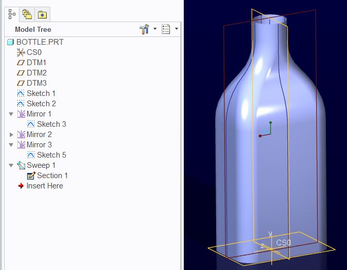
Frank, VSS is still there in Creo Parametric 2.0.
I've just tried to rebuild the sweep feature you've made in Creo 2 and it works well.
And back on topic:
I think this can't be done. I've tried to build the surface using 3 surface patches in Style feature.
This is what isocurves look like in comparison, which is ok, but as the next picture shows.
These 3 surfaces, or each connections in between are only of a tangency connectivity.
Why? Because when you try to switch this connection in Style from Tangency to Curvature, it switches back to Tangency by itself.
The reason is because it would fail if it didn't switch back. Because it's a nonsense to expect, in that particular direction, a linear (degree one) surface connecting to a radial (degree two) surface in curvature continuous manner, as there is only a tangency between the arcs and lines that make the border of this surface.
The sketched curves need to be curvature continuous first in order to create the whole thing as G2 surface, or else the surface as if made G2 by some feature that tweaks it, is never gonna follow these origin sketched curves.
If it doesn't make any sense to you, then try a curvature analysis on the sketched curves.
Feb 28, 2013
06:32 PM
- Mark as New
- Bookmark
- Subscribe
- Mute
- Subscribe to RSS Feed
- Permalink
- Notify Moderator
Please log in to access translation
Feb 28, 2013
06:32 PM
Jakub, please share the file you created for confirming the VSS. Mine is doing some very funny things.
Mar 01, 2013
09:12 AM
- Mark as New
- Bookmark
- Subscribe
- Mute
- Subscribe to RSS Feed
- Permalink
- Notify Moderator
Please log in to access translation
Mar 01, 2013
09:12 AM
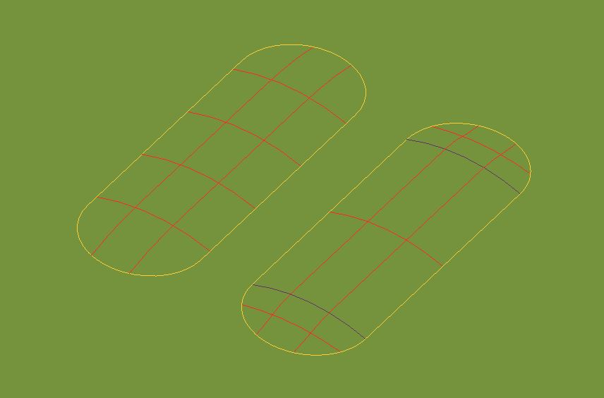
Here's variable section sweep and style surface side by side in one file.
(Creo 2.0 version)
Mar 01, 2013
09:28 AM
- Mark as New
- Bookmark
- Subscribe
- Mute
- Subscribe to RSS Feed
- Permalink
- Notify Moderator
Please log in to access translation
Mar 01, 2013
09:28 AM
Wish I could open that......
From your picture, it looks like the VSS gives the best representation so far. I'm going to change the arcs on the obround to conics and see where that takes us. I'd say the VSS with the conic top spine gets 90+% there, and the edge conics hopefully will make it even better. I think it really will, as after looking at the pic I posted of my "blue" model, the reflections look smoother on the domed section, and a little more abrupt on the edges closer to the obround, whic is what I'd expect since only the top spine ued a conic while the obround sketch used arcs.
Should have another shot at it soon.
Mar 01, 2013
10:14 AM
- Mark as New
- Bookmark
- Subscribe
- Mute
- Subscribe to RSS Feed
- Permalink
- Notify Moderator
Please log in to access translation
Mar 01, 2013
10:14 AM
I haven't done it yet, but this video makes me think the conic in every direction is the solution. Very interesting video, and shows that a conic will be very close to or CAN in some instances creat a C2 surface, and even eliminates some of the issues with other methods (inflections).
Mar 01, 2013
11:32 AM
- Mark as New
- Bookmark
- Subscribe
- Mute
- Subscribe to RSS Feed
- Permalink
- Notify Moderator
Please log in to access translation
Mar 01, 2013
11:32 AM
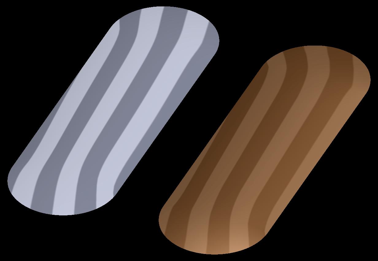
Ok, here's the latest and last stab at it. The surface is made with a VSS and with the exception of the spine, all the trajectory curves are conics with the rho vale for a perfect 90deg arc (use the sketcher section relation: rho = sqrt(2) - 1). If I used conics in the section of the VSS, it gave some funny artifacts at the curved edge, so the section was an arc driven by the 3 spines. I think this is a LITTLE better, but I think this is also the practical limit to Pro/E without the ISDX package. The grey surface is Pauls first STEP file, the bronze one is my latest. Have fun!
Mar 01, 2013
12:19 PM
- Mark as New
- Bookmark
- Subscribe
- Mute
- Subscribe to RSS Feed
- Permalink
- Notify Moderator
Please log in to access translation
Mar 01, 2013
12:19 PM
Wow, that one looks really nice and is pretty simple. Thanks everyone. I will see if I can get this shape approved.
Mar 01, 2013
12:32 PM
- Mark as New
- Bookmark
- Subscribe
- Mute
- Subscribe to RSS Feed
- Permalink
- Notify Moderator
Please log in to access translation
Mar 01, 2013
12:32 PM
Approved schmapproved, hope it works for ya! That should be good enough for even the finicky ID guys. I take it you were able to open it? Simplicity is always best if it works, so I'm happy with the way it turned out.
Be aware the VSS is a little tricky if you're swapping things out in the section. Sometimes you have to delete all the trajectories, and then redo the section if needed to get the references right. I think this was what Antonius was running into.
Good luck!
Mar 01, 2013
01:45 PM
- Mark as New
- Bookmark
- Subscribe
- Mute
- Subscribe to RSS Feed
- Permalink
- Notify Moderator
Please log in to access translation
Mar 01, 2013
01:45 PM
I'll be damned! In the section sketch, I was projecting the sweep section using a previous sketch which becomes a "sketch reference". You have to delete this sketch reference to have the VSS work.
This one really stumped me. Thanks for your help, Frank and Jakub!
Mar 01, 2013
05:02 PM
- Mark as New
- Bookmark
- Subscribe
- Mute
- Subscribe to RSS Feed
- Permalink
- Notify Moderator
Please log in to access translation
Mar 01, 2013
05:02 PM
Ok, I REALLY zoomed in on the surface, and it appears there's a slight inflectionor at least a curvature change at the very tip on both ends longitudinally. It's funny, tthe shape is smother than the ID surface, except in those tiny areas.
Hope that's not an issue for ya.
Mar 01, 2013
01:18 PM
- Mark as New
- Bookmark
- Subscribe
- Mute
- Subscribe to RSS Feed
- Permalink
- Notify Moderator
Please log in to access translation
Mar 01, 2013
01:18 PM
That's beautiful, Frank. I would have never even thought to look for the conics in sketcher Gotta love this forum!
Mar 01, 2013
03:07 PM
- Mark as New
- Bookmark
- Subscribe
- Mute
- Subscribe to RSS Feed
- Permalink
- Notify Moderator
Please log in to access translation
Mar 01, 2013
03:07 PM
Yeah, I forgot to mention that. The VSS will not vary section, or flat-out fail, if you've got a stationary reference from ANYTHING else. You can ONLY reference the trajectory references in the section.
Happy to help!
Mar 01, 2013
03:40 PM
- Mark as New
- Bookmark
- Subscribe
- Mute
- Subscribe to RSS Feed
- Permalink
- Notify Moderator
Please log in to access translation
Mar 01, 2013
03:40 PM
Oh, thanks I was having issues with that as well. In fact I am still having some issues with the VSS following the side curves, but I got something. I will post it below.
Feb 28, 2013
11:13 AM
- Mark as New
- Bookmark
- Subscribe
- Mute
- Subscribe to RSS Feed
- Permalink
- Notify Moderator
Please log in to access translation
Feb 28, 2013
11:13 AM
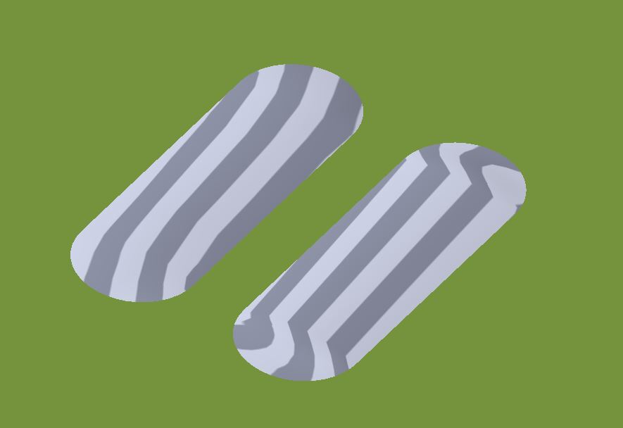
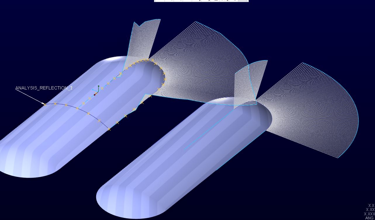
What is needed is a flat extrude through the center section with a part that tapers at each end. ID rejected the model that had revolved tangent ends because of the way light reflects off of it.
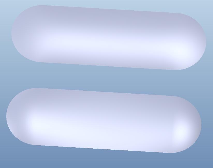
Frank, I was able to open your attachment. Here is a screenshot of what he wants that explains it better than I can with words.
The top model is the imported from SW and has the continuous curves. What the ID guy wants is the continuous light reflection and not the broken reflection shown in the bottom model.
I never made a statement that I did not have ISDX.
Feb 28, 2013
11:18 AM
- Mark as New
- Bookmark
- Subscribe
- Mute
- Subscribe to RSS Feed
- Permalink
- Notify Moderator
Please log in to access translation
Feb 28, 2013
11:18 AM
In looking at the STEP you posted, THEIR model isn't a flat extrude in the middle. There is a slight curve in it, but it's visible.
The model wanted was done in SW? Interesting, because SW generally does NOT have the surfacing control tools even in base Pro/E, not even close. Are they using some special ID package?
Try my new model and see. I made changes to it, and the reflection map looks almost perfectly identical, and in comparing the 2 side-by-side with the same color (unlike the blue shown), they look exactly the same to me oriented as you show.
If you have ISDX, you should be able to get C2.
And, as I mentioned, I think the ID people are too picky unless it's sheetmetal. Your mold tools are all polished, mostly by hand, so any imperfections are usually buffed out, and you'll get whatever the mold gives you anyways.
Feb 28, 2013
11:25 AM
- Mark as New
- Bookmark
- Subscribe
- Mute
- Subscribe to RSS Feed
- Permalink
- Notify Moderator
Please log in to access translation
Feb 28, 2013
11:25 AM
I understand that the original SW model was not flat in the center section. I am sure the ID guy did not notice that, but that is what he wants. If you look back up to my post from 12:35 yesterday you see where I fixed the non-flat center. When I created the flat sketch through the center section it made the end more tangent then continuous.
SW standard has a Filled Surface feature that allows you to fill a sketch while holding it to internal sketches for form. It is not that great of a surface, but it is what he used to show what he wanted.
Feb 28, 2013
11:29 AM
- Mark as New
- Bookmark
- Subscribe
- Mute
- Subscribe to RSS Feed
- Permalink
- Notify Moderator
Please log in to access translation
Feb 28, 2013
11:29 AM
Hmmmm, it's been a while since I used SW.
Of note, conics are a little tricky, but sometimes they are the only thing that will work. The nice thing is you can define end conditions (make sure you get what you really wanted), the angle(s), and the rho value to get things the way you want.
Hope this helps!
Feb 28, 2013
12:41 PM
- Mark as New
- Bookmark
- Subscribe
- Mute
- Subscribe to RSS Feed
- Permalink
- Notify Moderator
Please log in to access translation
Feb 28, 2013
12:41 PM
Sorry, I made the assumption about not having ISDX because you were having trouble getting this to work. I suspect the train of thought is completely different using ISDX. Since I don't have the module, I really cannot comment in that direction.
I did deconvolve the second step file. It is amazingly true to shape yet not really. I sectioned horizontally, and it left what would seem a perfect obround slot in each section; the true narrow section is not a true arc but rather is slightly depressed at 45/135 making for flatter tails. The spine's section is probably the real trick as it is carefully bound from the curve to the flat section. I didn't see a commonality in any of the sweeps either. It almost appears as a thickness change but its not.
So the remaining question may be how to capture the existing curves to use in sketches. That is something I was able to do. You can even give them the intelligence sought earlier. From there, they can saved and used. But whether or not they can be used to properly reconstruct the surface with the previously discussed methods is unclear.
Frank, I look forward to checking out your model. They open fine.
So where are the Creo ISDX guys here on the forum? I suspect they have a very simple solution.
Feb 28, 2013
01:13 PM
- Mark as New
- Bookmark
- Subscribe
- Mute
- Subscribe to RSS Feed
- Permalink
- Notify Moderator
Please log in to access translation
Feb 28, 2013
01:13 PM
Bart Brejcha, the main ISDX expert I know off the top of my head. I know he also has some cool tutorials on Youtube.
Feb 28, 2013
04:02 PM
- Mark as New
- Bookmark
- Subscribe
- Mute
- Subscribe to RSS Feed
- Permalink
- Notify Moderator
Please log in to access translation
Feb 28, 2013
04:02 PM
In order to have C2 continuity, the basic oblong shape cannot consist of two lines and two arcs.
Where the line meets the arc you will get C2 discontinuity by default. Any resulting surface will also have C2 discontinuity at this point.
the two arcs will have to be to curves with C2 continuity, instead.
This can be achieve by creating curves thru points and setting curvature at the ends.
I think it is a lot easier to create this in ISDX....
Feb 28, 2013
04:37 PM
- Mark as New
- Bookmark
- Subscribe
- Mute
- Subscribe to RSS Feed
- Permalink
- Notify Moderator
Please log in to access translation
Feb 28, 2013
04:37 PM
Interesting. Perhaps use conics for the oblong shape and just set the rho value to be an arc?
I think I got 99% of what Paul had just by eyeballing it relative to his STEP file.
Feb 28, 2013
05:43 PM
- Mark as New
- Bookmark
- Subscribe
- Mute
- Subscribe to RSS Feed
- Permalink
- Notify Moderator
Please log in to access translation
Feb 28, 2013
05:43 PM
That's right.
Feb 28, 2013
07:09 PM
- Mark as New
- Bookmark
- Subscribe
- Mute
- Subscribe to RSS Feed
- Permalink
- Notify Moderator
Please log in to access translation
Feb 28, 2013
07:09 PM
JORGEN LINDQVIST wrote:
In order to have C2 continuity, the basic oblong shape cannot consist of two lines and two arcs.
Where the line meets the arc you will get C2 discontinuity by default. Any resulting surface will also have C2 discontinuity at this point.
the two arcs will have to be to curves with C2 continuity, instead.
This can be achieve by creating curves thru points and setting curvature at the ends.
I think it is a lot easier to create this in ISDX....
Jorgen, there is definitely something behind what you are saying. I created two versions side by side. The left version uses construction curves (line and arc) on which points were located and tangency features on the
ends. On top of this was laid the spline with the ends tangent to ensure continuity. This was done for all 4 sections.
The surface on the right was one with arcs and lines throughout. You could see a small difference in the default surface quality in config.pro but when changed from 3 to 50, the difference was really pronounced.
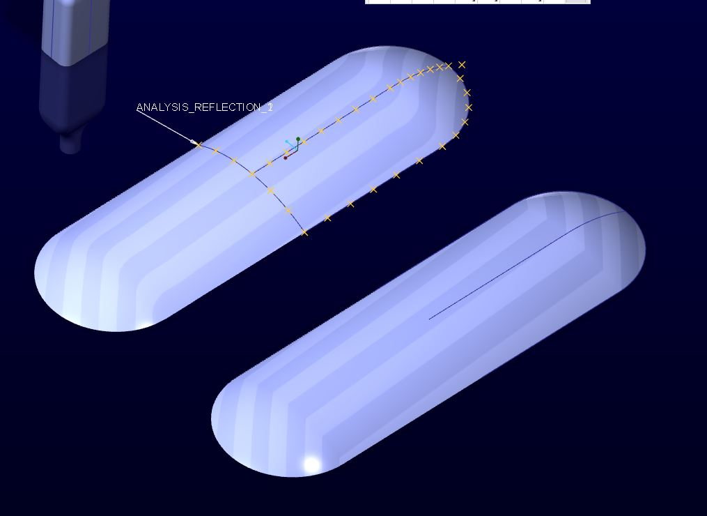
This is an example of one of the sections... all were done similarly.
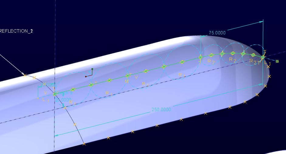
Unfortunately, Creo won't let you see the curves well enough to determine how close the spline follows the lines and arcs. But visually, they are round and straight. I know by definition they cannot be.
Feb 28, 2013
07:16 PM
- Mark as New
- Bookmark
- Subscribe
- Mute
- Subscribe to RSS Feed
- Permalink
- Notify Moderator
Please log in to access translation
Feb 28, 2013
07:16 PM
Hey Antonius, it's funny, but when I'm just logged in a guest, you show up as: TomD.inPDX
Anyways, I think I'm going to try and do the obround (oblong) curve with conics instead of the arcs, since when I used a conic on the top/3rd trajectory curve, it made things a lot better. Interesting. Weird how an arc, which SHOULD be perfect (since it's nothing more than a section of the end of the long surf), somehow isn't.
Too bad the VSS doesn't work for you, that's a real drag.....
Feb 28, 2013
07:23 PM
- Mark as New
- Bookmark
- Subscribe
- Mute
- Subscribe to RSS Feed
- Permalink
- Notify Moderator
Please log in to access translation
Feb 28, 2013
07:23 PM
I think it is working, just not the same. Looking forward to Jakub's version.
This is also in support of Jorgen's observation:
That just confirms that the ID guys just hate perfection
Feb 28, 2013
07:20 PM
- Mark as New
- Bookmark
- Subscribe
- Mute
- Subscribe to RSS Feed
- Permalink
- Notify Moderator
Please log in to access translation
Feb 28, 2013
07:20 PM
Hey thanks for working on this so much everyone. I have been swapped with other things today so I have not been able to work on it much. Hope everyone has a good evening.
Feb 28, 2013
07:23 PM
- Mark as New
- Bookmark
- Subscribe
- Mute
- Subscribe to RSS Feed
- Permalink
- Notify Moderator
Please log in to access translation
Feb 28, 2013
07:23 PM
It has been a very interesting discussion, Paul.
Feb 28, 2013
07:25 PM
- Mark as New
- Bookmark
- Subscribe
- Mute
- Subscribe to RSS Feed
- Permalink
- Notify Moderator
Please log in to access translation
Feb 28, 2013
07:25 PM
Second that. When I get time, I'm going to try and cheat with 2 more conics and see what happens. I'm thinking that MIGHT work to get that last 1% perfection.
G'nite y'all....


