Turn on suggestions
Auto-suggest helps you quickly narrow down your search results by suggesting possible matches as you type.
Showing results for
Please log in to access translation
Turn on suggestions
Auto-suggest helps you quickly narrow down your search results by suggesting possible matches as you type.
Showing results for
Community Tip - Need to share some code when posting a question or reply? Make sure to use the "Insert code sample" menu option. Learn more! X
- Community
- Creo+ and Creo Parametric
- 3D Part & Assembly Design
- Re: Filled text
Translate the entire conversation x
Please log in to access translation
Options
- Subscribe to RSS Feed
- Mark Topic as New
- Mark Topic as Read
- Float this Topic for Current User
- Bookmark
- Subscribe
- Mute
- Printer Friendly Page
Filled text
Jun 17, 2014
06:29 AM
- Mark as New
- Bookmark
- Subscribe
- Mute
- Subscribe to RSS Feed
- Permalink
- Notify Moderator
Please log in to access translation
Jun 17, 2014
06:29 AM
Filled text
Hello
I´m modeling electrical enclosures and labels for them with Creo Parametric 2.0. I´m trying to make them by modeling a label base where necessary texts are cut extruded. Then I make a drawing and print it to the aluminum foil. Obviously by using this "technique" only outlines of the text is printed and the gaps between the text outlines are so small that the result is not looking very nice.
The question:
Is there way to put a filled text into a planar surface of a part? I know that I could add a text in to the drawing but then the text wouldn´t follow the model and copy pasting the model to the next project wouldn´t work.
31 REPLIES 31
Jun 17, 2014
06:42 AM
- Mark as New
- Bookmark
- Subscribe
- Mute
- Subscribe to RSS Feed
- Permalink
- Notify Moderator
Please log in to access translation
Jun 17, 2014
06:42 AM
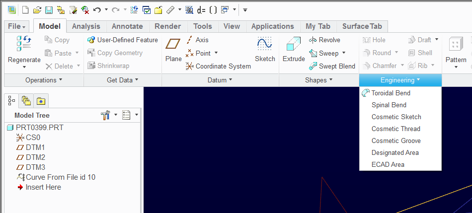
The method I use to put text, logos, or any other graphics onto the surface(s) of a part is the "Cosmetic Groove", which is under the "Engineering" (I don't know why) tab. You pick the surface(s) you want your geometry to be on, then sketch the stuff you want projected onto the surface. Planar surfaces are the easiest, but I've used this a lot on all sorts of curved surfaces. The reason I use "Cosmetic Groove", generally, is because I can use these types of features to engrave the parts using the manufacturing module.
A recent improvement to Creo is the ability to use a parameter for the text in the sketch, which makes it really easy to have family table parts that have unique text such as part numbers, etc.
Hopefully this is what you were seeking. I don't know if a lot of attention is paid to this type of feature in the general Creo userbase, but I use it a lot.
Jun 17, 2014
07:19 AM
- Mark as New
- Bookmark
- Subscribe
- Mute
- Subscribe to RSS Feed
- Permalink
- Notify Moderator
Please log in to access translation
Jun 17, 2014
07:19 AM
Thanks for the answer but I can get only outlined text with this method. Is there way to fill the text?
Jun 17, 2014
09:11 AM
- Mark as New
- Bookmark
- Subscribe
- Mute
- Subscribe to RSS Feed
- Permalink
- Notify Moderator
Please log in to access translation
Jun 17, 2014
06:59 PM
- Mark as New
- Bookmark
- Subscribe
- Mute
- Subscribe to RSS Feed
- Permalink
- Notify Moderator
Please log in to access translation
Jun 17, 2014
06:59 PM
David's link will give you options.
This is one method to consider:
- Create the nomenclature in a sketch.
- Create a Fill feature by projecting the geometry of the note sketch.
Otherwise, yes, you can extrude the original sketch to create a solid.
I prefer the solid option; but be aware of accuracy issues. I also prefer to make the "silkscreen" a separate part assembled in the next level.
Jun 17, 2014
09:57 AM
- Mark as New
- Bookmark
- Subscribe
- Mute
- Subscribe to RSS Feed
- Permalink
- Notify Moderator
Please log in to access translation
Jun 17, 2014
09:57 AM
Cosmetics are pretty worthless IMPO. I use sketched datum curves exclusively for this type of thing, making labels, doing silkscreens, and such. You can make the curve have hatching (you have to go back into it and add the option - really stupid), and then at the dwg level you just make the hatch spacing so small it prints solid. Bing able to use parameters in sketch mode (sometimes driven by relations and/or other parameters - model_name, and Windchill revision etc.) is awesome.
Good luck!
Jun 18, 2014
07:06 AM
- Mark as New
- Bookmark
- Subscribe
- Mute
- Subscribe to RSS Feed
- Permalink
- Notify Moderator
Please log in to access translation
Jun 18, 2014
07:06 AM
But can you use datum curves to make a feature that has a complex logo and included identification text, projected onto a contoured surface, and then use it for engraving? I've always used the cosmetic groove stuff to do this, so I can mark contoured surfaces with a ball endmill. It's been a while since I tried any other method because this one has not let me down.
Jun 18, 2014
09:49 AM
- Mark as New
- Bookmark
- Subscribe
- Mute
- Subscribe to RSS Feed
- Permalink
- Notify Moderator
Please log in to access translation
Jun 18, 2014
09:49 AM
You can project or wrap a datum curve. Complex logo's are going to be tough in any feature if you're trying to have a bunch of entities in a sketch. You might have to make several sketches. I made these labels in Pro/E, and made some curved ones as well, I just can't find the images. You can also float a surface .002 or so off a solid surface for silkscreening. 
Jun 18, 2014
09:54 AM
- Mark as New
- Bookmark
- Subscribe
- Mute
- Subscribe to RSS Feed
- Permalink
- Notify Moderator
Please log in to access translation
Jun 18, 2014
09:54 AM
I'd imaging that if you can project or wrap a cosmetic feature onto your contoured surface, you can do it with a curve. Not sure if the hatch thing will work on a projected or wrapped curve, somehow I don't think you can.
A pic of a finished part showing what you're trying to do would work wonders. 
Jun 18, 2014
04:32 PM
- Mark as New
- Bookmark
- Subscribe
- Mute
- Subscribe to RSS Feed
- Permalink
- Notify Moderator
Please log in to access translation
Jun 18, 2014
04:32 PM
You have way to much fun in your work, Frank. They actually pay you for this artwork? 
Jun 19, 2014
10:12 AM
- Mark as New
- Bookmark
- Subscribe
- Mute
- Subscribe to RSS Feed
- Permalink
- Notify Moderator
Please log in to access translation
Jun 19, 2014
10:12 AM
.....I invented the "Woodward swoosh"!
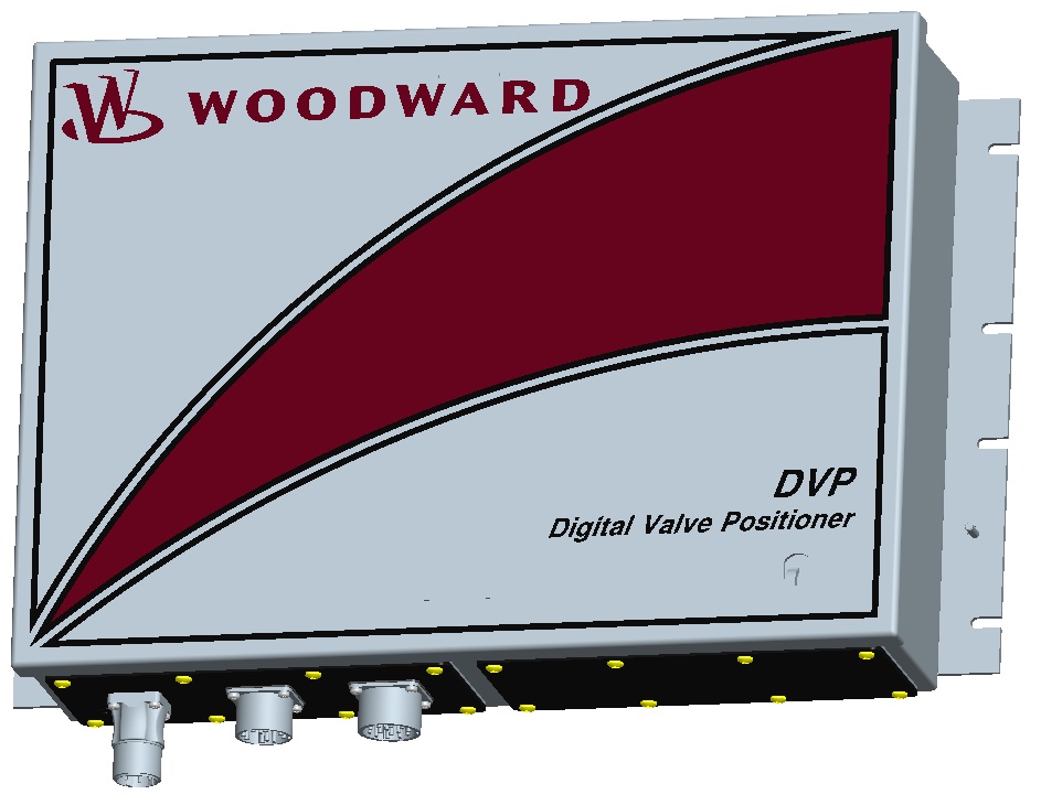
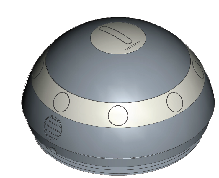
The die-casting was kinda fun. Got to design a high-voltage (20 kv) enclosure and drive the design of the electronics packaging in tandem. Got to extrude the logo and ground symbol in the casting (turned out sweet!) and do the labels too. Sometimes you get to have a little fun!
Jun 18, 2014
04:31 PM
- Mark as New
- Bookmark
- Subscribe
- Mute
- Subscribe to RSS Feed
- Permalink
- Notify Moderator
Please log in to access translation
Jun 18, 2014
04:31 PM
Datum curves are actually quite limited:
- Through points
- From Equation -or-
- from Cross Section
However, Cosmetic Curves are simply sketches or filled sketches (area).
The only way to have complex curve data that is not fully constrained in a sketch is to import a DXF or DWG file into a part. This remains an "import feature" and does not require full dimensional detail as a sketch does.
The more practical way to manage complex detail curves is through a symbol. Symbols act more like drawings, meaning that curves drawn are not parametric. Symbols are annotation so they can be added to a model but in my opinion, are difficult to manage in models. But if it is a logo that will be used in many different ways, it is a good way to manage it as an option when appropriate. The only limitation to symbols is that you cannot use them as underlays for projected curves into sketches. (I may have gone way over people's heads by now, but I wanted to post all options).
When I created a PTC logo, I left the definition with weak dimensions in the sketch.
![]()
You have to be careful in how you use it, but it has served well with appropriate attention.
If you wish to clearly define your requirements, we might be able to come up with a good method. Again, as with everything with PTC, there are -many- ways to do something. There is no -best- or -right- way.
Jun 19, 2014
10:08 AM
- Mark as New
- Bookmark
- Subscribe
- Mute
- Subscribe to RSS Feed
- Permalink
- Notify Moderator
Please log in to access translation
Jun 19, 2014
10:08 AM
....and sketched. That's what I meant. I've successfully imported artwork from an AutoCAD dwg, into a Pro/E dwg, and used those line/spline/acr elements copied into a datum curve sketch. That's how I did those woodward logos.
I don't like cosmetics because they don't work for screen shots (unless they fixed that), they show THRU the solid part. Also, you can't use that geometry for anything else or to reference. I've never found something that a cosmetic was able to do that I couldn't do with a sketched curve, but maybe I'm missing something. Haven't played with cosmetics for a while.
The silkscreen I did on the box was 2 separate surface models, one for each color, and they in fact did shoot the artwork from a DXF of the dwg I preovided. The actual silkscreen models are instances that reference model geometry at the assy level, so if a hole is moved, or the size changes, the silkscreen changes with it. This was a huge problem at the company I develpoped. They had an art program for the silk screen, but they had almost no control over the actual numerical location of the text, so many times it was trial and error, shooting and re-shooting the screen, and many times even then you had to try and manuall line up the screen as best you could, knowing some text was not going to be centered over the holes they should be perfectly aligned to. This fixed all that. It was a fun little project, originally way back in '00. The Woodward stuff shown I did in about '08 or so.
Jun 19, 2014
01:47 PM
- Mark as New
- Bookmark
- Subscribe
- Mute
- Subscribe to RSS Feed
- Permalink
- Notify Moderator
Please log in to access translation
Jun 19, 2014
01:47 PM
you won't like this in Creo either...
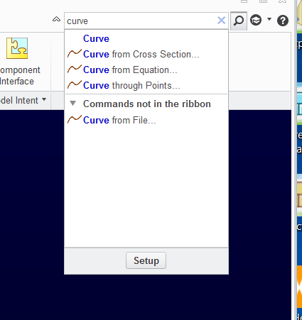
I don't see a "curve from sketch" but there is a hidden "curve from file"
Jun 19, 2014
03:09 AM
- Mark as New
- Bookmark
- Subscribe
- Mute
- Subscribe to RSS Feed
- Permalink
- Notify Moderator
Please log in to access translation
Jun 19, 2014
03:09 AM
Thanks all for the answers.
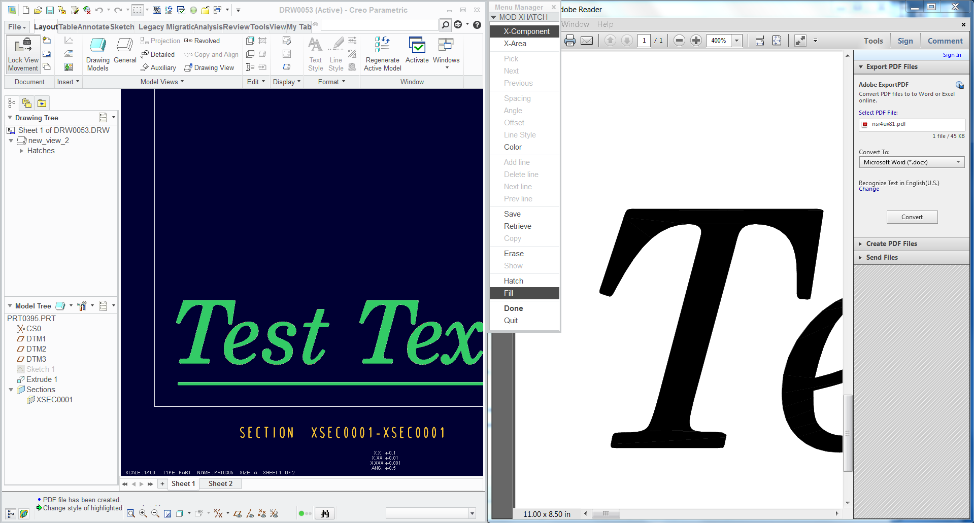
Below is shown the printed drawing in to the aluminum foil. Drawing is made from a part where sketch is extruded to the label base. Geometry line thickness is too wide but not enough to fill all of the center areas. Result is blurry and messy.
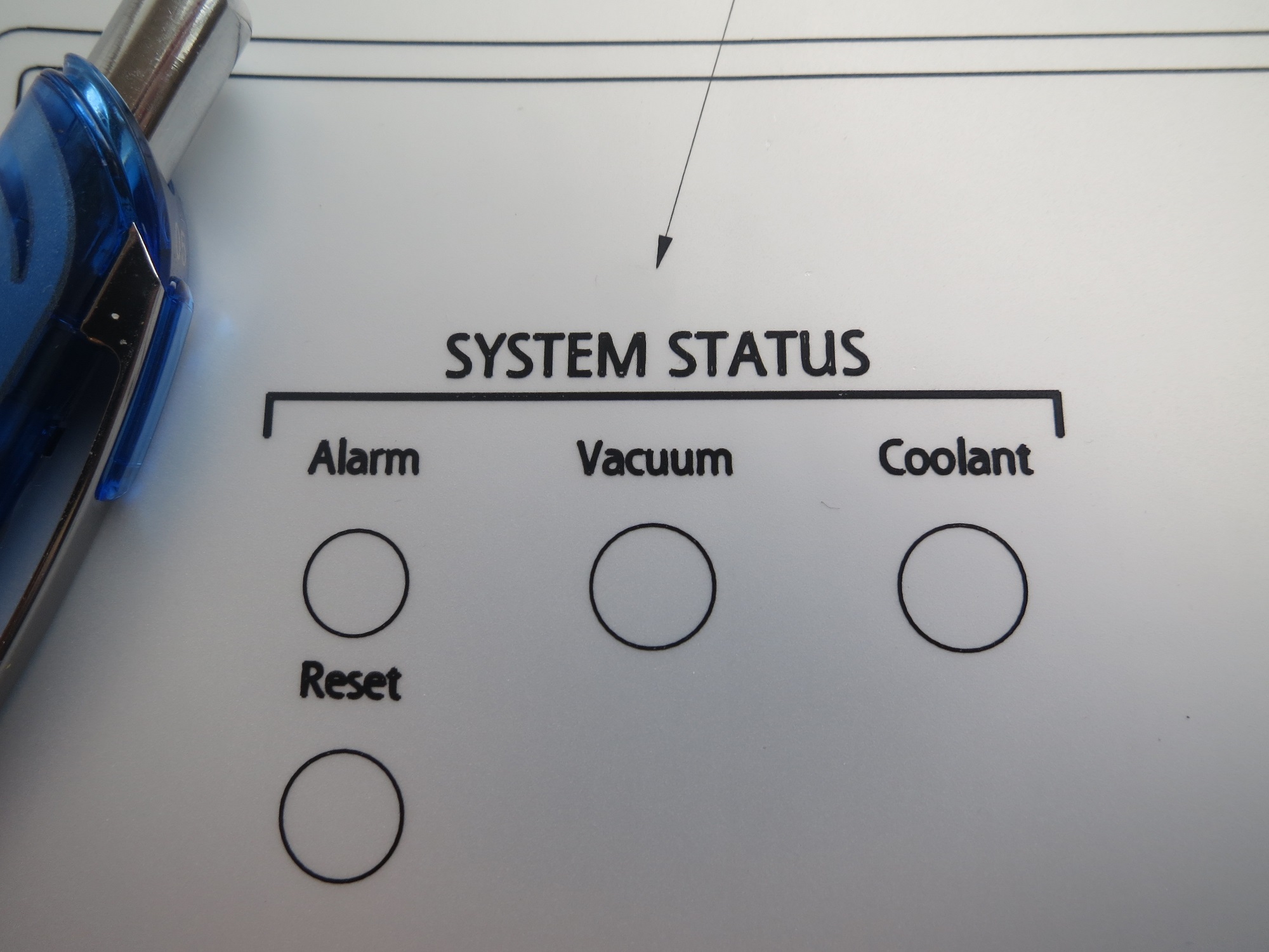
When I make an annotation note in drawing, the result would be accurate enough for me (see another photo), but then the texts will not follow the model and the placement handling is not so flexible as it is in part level when feature is sketched. Also drawing notes are not shown in assembly.

I copy paste these labels all the time and modify them so easy handling speed is needed. Maybe Creo is not the right platform to do these things but I have been happy that I can modify the panel cut outs and these labels at the same time and see the result in assembly.
Propably filling the text is not even a solution. I would need accurate printable text somehow in to the part´s surface.
Jun 19, 2014
03:44 AM
- Mark as New
- Bookmark
- Subscribe
- Mute
- Subscribe to RSS Feed
- Permalink
- Notify Moderator
Please log in to access translation
Jun 19, 2014
03:44 AM
I am glad you provided the additional information.
This is a separate problem.
The problem is that the text gets assigned a pen thickness that is added to the outline of the text.
This can be solved with pen tables.
So pick a method of making the text solid... filled geometry or extruded solids.
When you print the drawing, use a pen table to manage thickness of the printing (very thin!)
This works for your line art as well. Make it to the size you want and set the pen thickness to .001" for instance.
You probably need to print using drawing views with "shaded" views. I have also created shaded views under hidden line views to make the outlines crisper. Setting the environment to black and white, you will get very good output.
Are you printing directly to a printer or to a PDF output? I am not as familiar with direct printing outputs but I know I can get there with PDF.
If you want, you can attach the file to these messages by using the advanced editor (upper right of the reply dialog). I can show you what can be done with PDF without too much effort.
Jun 19, 2014
03:45 AM
- Mark as New
- Bookmark
- Subscribe
- Mute
- Subscribe to RSS Feed
- Permalink
- Notify Moderator
Please log in to access translation
Jun 19, 2014
03:45 AM
And you may be right, this is certainly not the tool to make "camera ready art" but it can be made to work for the specific instance you are looking for.
Jun 19, 2014
04:22 AM
- Mark as New
- Bookmark
- Subscribe
- Mute
- Subscribe to RSS Feed
- Permalink
- Notify Moderator
Please log in to access translation
Jun 19, 2014
04:22 AM
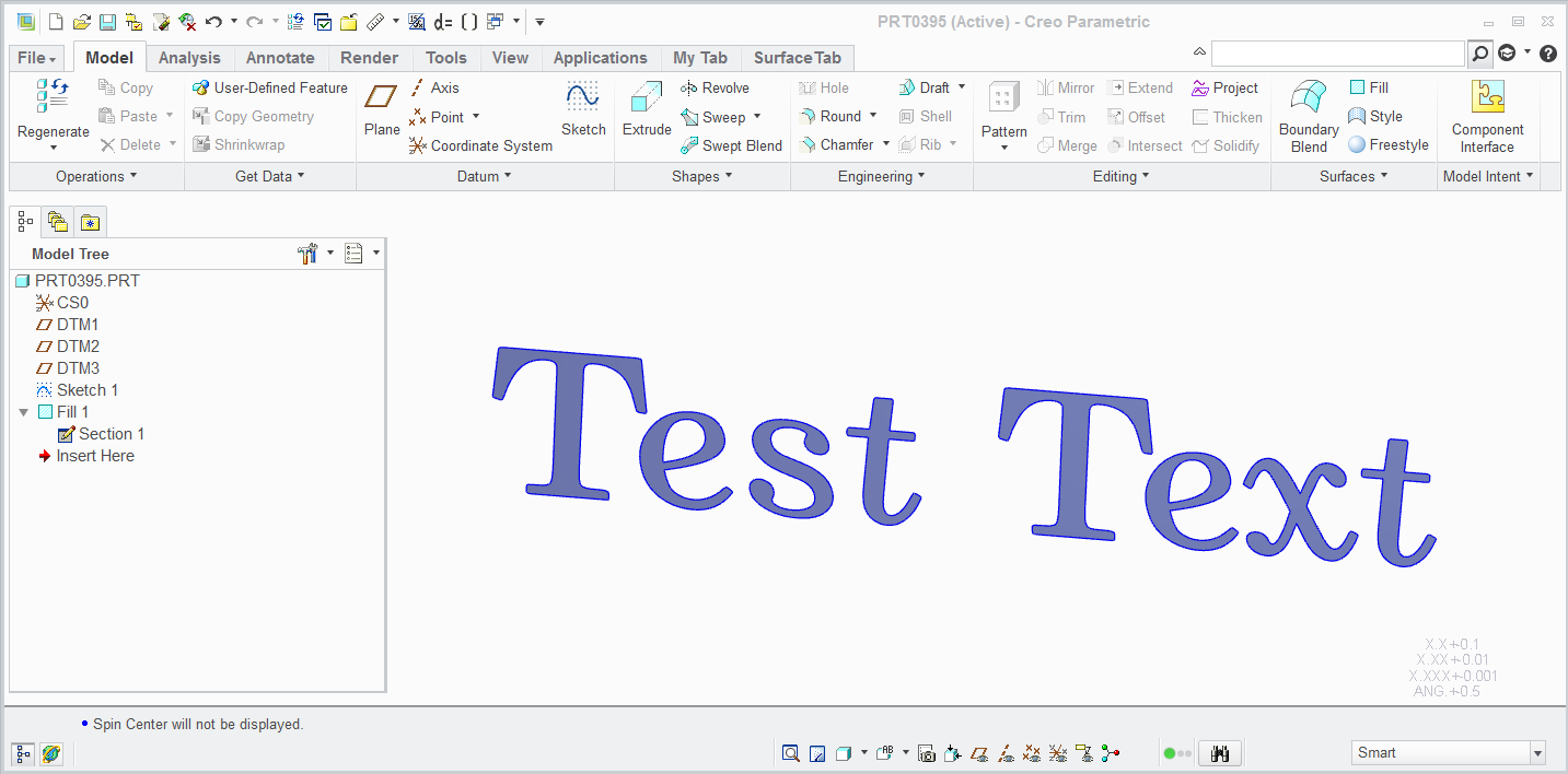
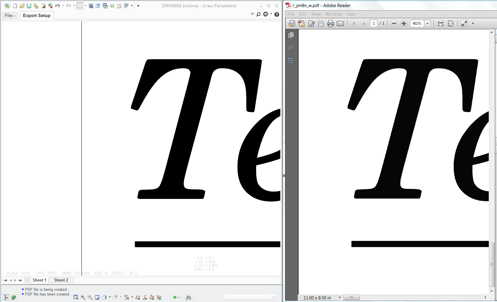
There are a few tricks in how to achieve this but this is a comparison of the 3D model (cosmetic fill of 3D text); CAD view in a drawing; output PDF; which can be achieved. Not even close to perfect in my book, but certainly does what I tell it to do. Again, I don't know how well this would go directly to a printer or even if a pen table can be used for direct printing. Others will help you with that.
Jun 19, 2014
05:59 AM
- Mark as New
- Bookmark
- Subscribe
- Mute
- Subscribe to RSS Feed
- Permalink
- Notify Moderator
Please log in to access translation
Jun 19, 2014
05:59 AM
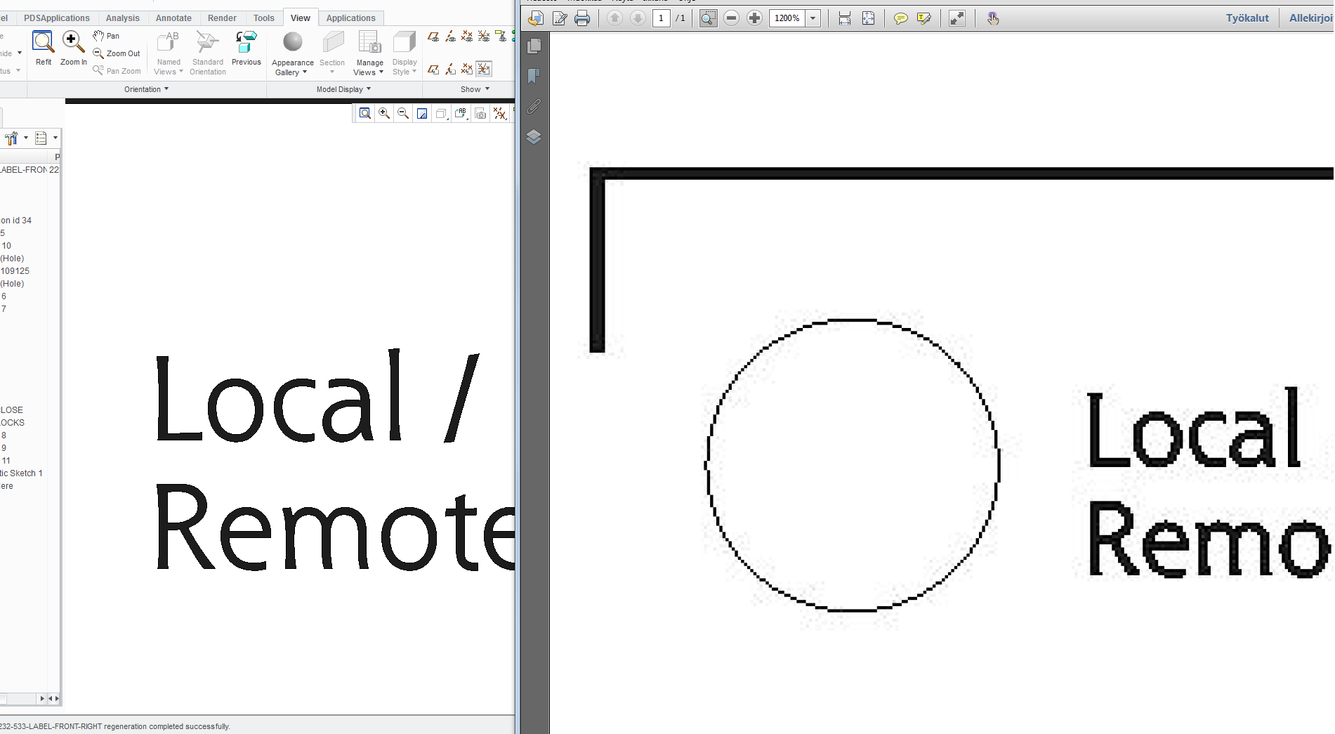
I´m using pdf export from drawing. View is "shaded with edges" and pdf output is 600dpi. Using pen table or not doesn´t seem to make the difference to the result in pdf exporting. I changed model´s absolute accuracy to the finest as possible. I don´t get why pdf looks like it is heavily compressed.
This what I got. I almost nailed it .
.
How do you create pdf?
Jun 19, 2014
11:36 AM
- Mark as New
- Bookmark
- Subscribe
- Mute
- Subscribe to RSS Feed
- Permalink
- Notify Moderator
Please log in to access translation
Jun 19, 2014
11:36 AM
Ouch! Yes, PDF uses a JPG type of compression technique. I am very disappointed in this with most things related to graphic art. However, you have the right technique but it still needs a little work.
I use the File/saveas/export dialog to get to the PDF creation and use a pen table in my working folder named table.pnt. I can change this on the fly for whatever I need at the moment, and it is picked up without worrying about -which- pentable is being used for other sessions.
I am going to suggest that the next step requires scaling your artwork. This goes against what you are trying to accomplish (1:1 art) but it will improve the edges. You can always print to foil your PDF as 25% scale or even 10%. You could try just scaling up your drawing view scale to 4-10x, but I am not sure if this will suffice.
Also, the shaded with edges is a very poor approximation in PDF. If you overlay a wireframe view (managed by origin) you will see how the shaded view is not filling the -void- perfectly.
In general, the output is always about making drawings, not artwork. Much of this is driven by the printer you choose. PDF is probably a poor printer choice. We use to have a pretty good TIFF print option but even that has been compromised.
If you really want quality edges, you probably want to output the drawing as a DXF and import it to something like photoshop and make the edges filled there. You have much greater control over the output in this way.
Hopefully someone else will weigh in here that has done this in a production environment. I can only touch on the basics as I've experienced them.
Jun 19, 2014
12:22 PM
- Mark as New
- Bookmark
- Subscribe
- Mute
- Subscribe to RSS Feed
- Permalink
- Notify Moderator
Please log in to access translation
Jun 19, 2014
12:22 PM
I did datum curves with hatch, set to look "filled", and exported the DXF of the dwg to shoot the artwork. Worked great, and just like the pic I posted. PDF's are junk.
Jun 19, 2014
01:49 PM
- Mark as New
- Bookmark
- Subscribe
- Mute
- Subscribe to RSS Feed
- Permalink
- Notify Moderator
Please log in to access translation
Jun 19, 2014
01:49 PM
I did datum curves with hatch, set to look "filled", and exported the DXF of the dwg to shoot the artwork. Worked great, and just like the pic I posted. PDF's are junk.
Can't find this one either.
Jun 19, 2014
02:15 PM
- Mark as New
- Bookmark
- Subscribe
- Mute
- Subscribe to RSS Feed
- Permalink
- Notify Moderator
Please log in to access translation
Jun 19, 2014
02:15 PM
Frank, I think you will find that datum curves have been replaced with cosmetic features. They have added intent curves in the datum region to designate cosmetic curves (and other edges or curves) as designated datum "intent" references.
I also do not see a hatch in part mode. They now have the "fill" cosmetic. I know what you are talking about because I remember using it in the past. That would be an excellent solution to this issue sinced you can have curves (hatch) print "solid" where the shaded view is not satisfactory in quality.
Jun 19, 2014
02:21 PM
- Mark as New
- Bookmark
- Subscribe
- Mute
- Subscribe to RSS Feed
- Permalink
- Notify Moderator
Please log in to access translation
Jun 19, 2014
02:21 PM
I thought the Sketched Datum Curve was replaced by the Sketch feature.
There has always been a Cosmetic Sketch, back to Rev 12.
Jun 19, 2014
04:52 PM
- Mark as New
- Bookmark
- Subscribe
- Mute
- Subscribe to RSS Feed
- Permalink
- Notify Moderator
Please log in to access translation
Jun 19, 2014
04:52 PM
In my non-current version it's under: "Insert, Model Datum, Sketch".
I just did a quick test. You cannot xhatch a projected curve, and you cannot xhatch a projected cosmetic. But with the datum curve, at least I can reference the geometry later for other features, which you cannot do with a cosmetic. You can't even measure to it. This is the primary reason I use curves vs. cosmetics, the graphics issue 9seeing the cosmetic thru the part) is a close second why.
It would be a nice upgrade if projected and wrapped curves and cosmetics could be xhatched. If not, I just offset a surface .001 or so and trim it, and make it whatever color I need.
Jun 19, 2014
02:17 PM
- Mark as New
- Bookmark
- Subscribe
- Mute
- Subscribe to RSS Feed
- Permalink
- Notify Moderator
Please log in to access translation
Jun 19, 2014
02:17 PM
A little mean spirited about PDF, since most of the printing and publishing industry relies on the format, one that encompasses far more than most imagine.
Perhaps what PTC does with PDF is junk, though they do so little it's hard to see how they can ruin it.**
Something in particular that's not to like?
**The JPEG compression looks bad, but there are other compression formats available to PDF creators.
From Wikipedia http://en.wikipedia.org/wiki/Portable_Document_Format#Raster_images
- ASCII85Decode a filter used to put the stream into 7-bit ASCII
- ASCIIHexDecode similar to ASCII85Decode but less compact
- FlateDecode a commonly used filter based on the zlib/deflate algorithm (a.k.a. gzip, but not zip) defined in RFC 1950 and RFC 1951; introduced in PDF 1.2; it can use one of two groups of predictor functions for more compact zlib/deflate compression: Predictor 2 from the TIFF 6.0 specification and predictors (filters) from the PNG specification (RFC 2083)
- LZWDecode a filter based on LZW Compression; it can use one of two groups of predictor functions for more compact LZW compression: Predictor 2 from the TIFF 6.0 specification and predictors (filters) from the PNG specification
- RunLengthDecode a simple compression method for streams with repetitive data using the Run-length encoding algorithm and the image-specific filters
- DCTDecode a lossy filter based on the JPEG standard
- CCITTFaxDecode a lossless bi-level (black/white) filter based on the Group 3 or Group 4 CCITT (ITU-T) fax compression standard defined in ITU-T T.4 and T.6
- JBIG2Decode a lossy or lossless bi-level (black/white) filter based on the JBIG2 standard, introduced in PDF 1.4
- JPXDecode a lossy or lossless filter based on the JPEG 2000 standard, introduced in PDF 1.5
Jun 19, 2014
02:28 PM
- Mark as New
- Bookmark
- Subscribe
- Mute
- Subscribe to RSS Feed
- Permalink
- Notify Moderator
Please log in to access translation
Jun 19, 2014
02:28 PM
David Schenken wrote:
Perhaps what PTC does with PDF is junk, though they do so little it's hard to see how they can ruin it.**
Fair enough
Jun 19, 2014
02:35 PM
- Mark as New
- Bookmark
- Subscribe
- Mute
- Subscribe to RSS Feed
- Permalink
- Notify Moderator
Please log in to access translation
Jun 19, 2014
02:35 PM
David, if you look closely at PDF prints that have both a shaded images and a wireframe image overlayed directly, you will find that the output of the shaded image matching is really poor along the much crisper wireframe. It is simply not a very good output even though the views are explicitly aligned.
This is where I 1st noticed it:
The shaded views are seriously tessellated along non-linear curves.
Jun 19, 2014
02:47 PM
- Mark as New
- Bookmark
- Subscribe
- Mute
- Subscribe to RSS Feed
- Permalink
- Notify Moderator
Please log in to access translation
Jun 19, 2014
02:47 PM
Darn, Frank! Of course, as always, you have a genius insight.
Marko; extrude the artwork as a solid and define a section through the artwork (stay with me...)
In the drawing, display the view in a drawing as a section.
Edit the section (model tab; highlight the hatch; properties) and change the hatch to "fill".
Print monochrome with a very thin pen thickness in the pentable, and whallah! Really crisp edges.
You might still consider the scaling option since that can only help matters in the print function.
Also, change this setting in your adobe reader:

(uncheck this option!)
Jun 19, 2014
05:54 PM
- Mark as New
- Bookmark
- Subscribe
- Mute
- Subscribe to RSS Feed
- Permalink
- Notify Moderator
Please log in to access translation
Jun 19, 2014
05:54 PM
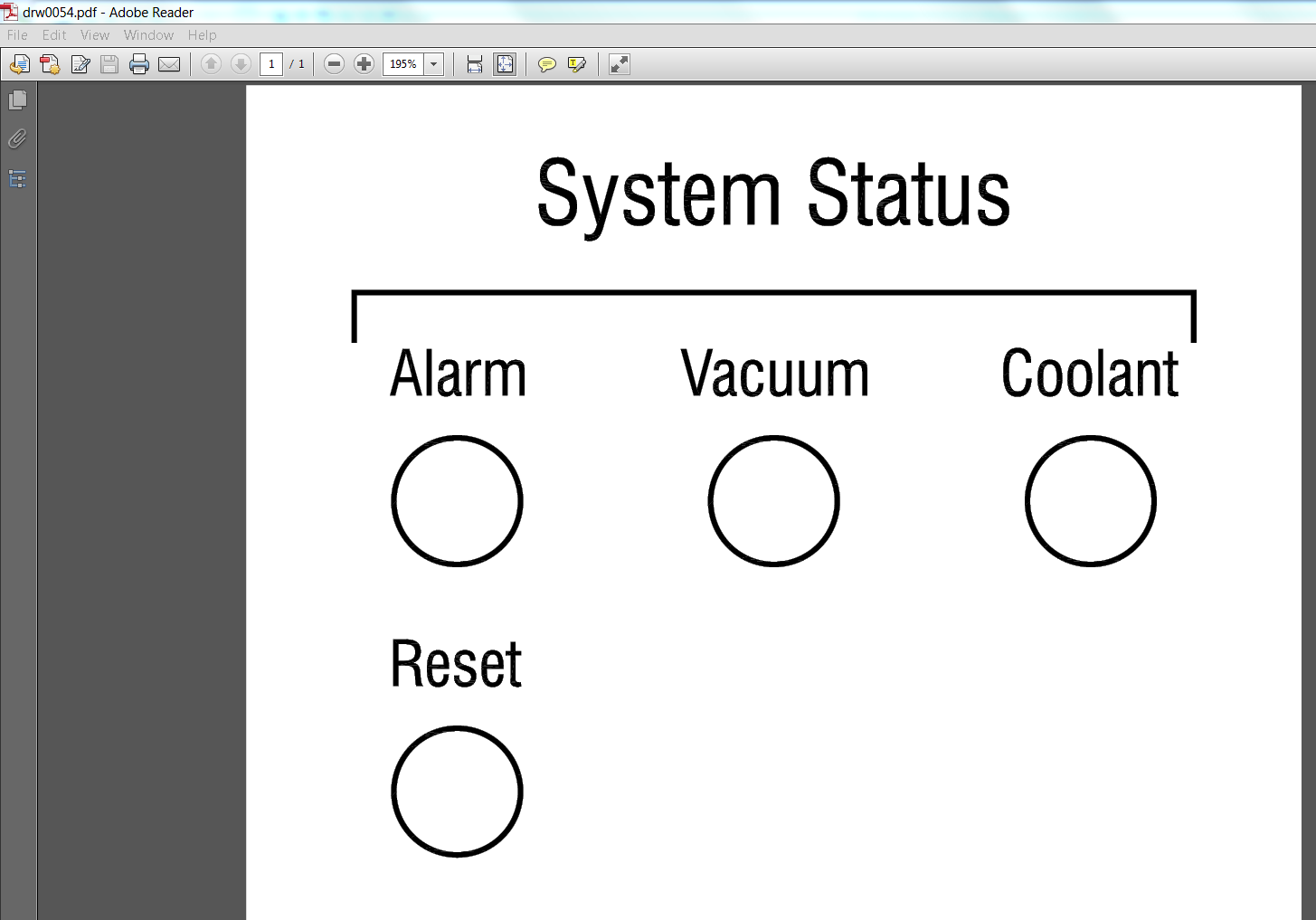
Take a look at the attached PDF...
Scale: 1:1, Line weight .025"; font (Swiss condenced) .22 high; circles .625" OD
In order to get this to extrude, I had to change the part accuracy to .0005"