
Turn on suggestions
Auto-suggest helps you quickly narrow down your search results by suggesting possible matches as you type.
Showing results for
Please log in to access translation
Turn on suggestions
Auto-suggest helps you quickly narrow down your search results by suggesting possible matches as you type.
Showing results for
- Community
- Creo+ and Creo Parametric
- 3D Part & Assembly Design
- Re: Filling gaps on surface profile
Translate the entire conversation x
Please log in to access translation
Options
- Subscribe to RSS Feed
- Mark Topic as New
- Mark Topic as Read
- Float this Topic for Current User
- Bookmark
- Subscribe
- Mute
- Printer Friendly Page
Filling gaps on surface profile
Dec 09, 2014
03:35 AM
- Mark as New
- Bookmark
- Subscribe
- Mute
- Subscribe to RSS Feed
- Permalink
- Notify Moderator
Please log in to access translation
Dec 09, 2014
03:35 AM
Filling gaps on surface profile
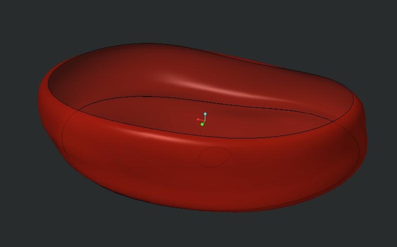
I wanted to create an irregular shape of human disc using the surface feature. I manage to construct the shape as per the sequence below:
1) Boundary blend at the wall area
2) Boundary blend at the top surface
3) Boundary blend at the bottom surface
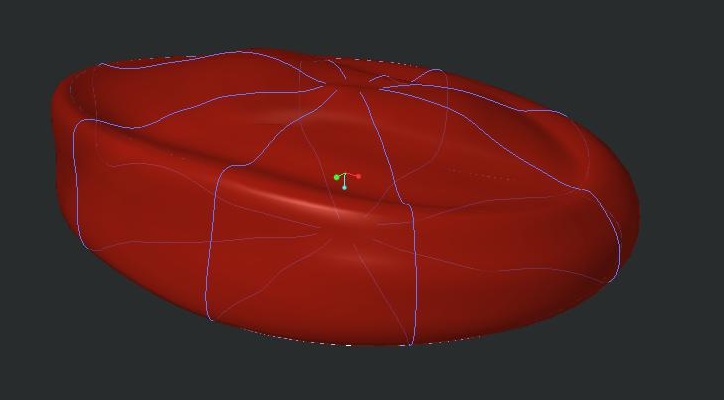
The blue line is the sketch reference used for the boundary blend feature.
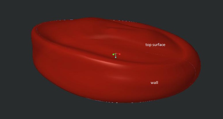
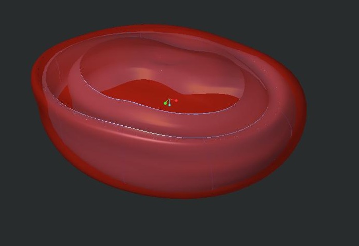
The final shape that I manage to construct.
I wanted to SOLIDIFY the image so that I can assign material properties to the structure -- but, it failed. I assumed it may be caused by gaps coexisted between the TOP - WALL - BOTTOM boundary. So I figured maybe I can export this file to .stp file, reimport the file with PTC Parametric and utilise the IDD (Import Data Doctor) to close any possible gaps.
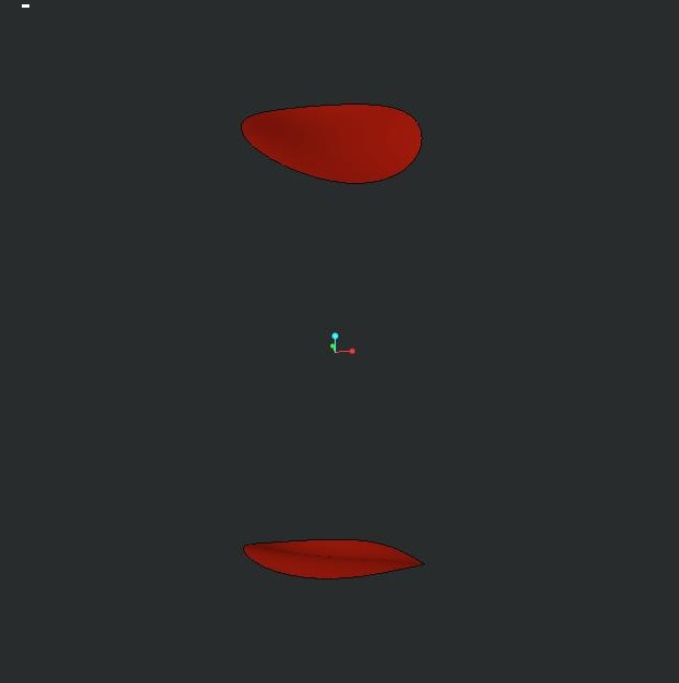
However, when exporting the surface to .stp (or iges.) format, it only export the little two circle (see image below) which was created using style > surface feature. WHY WHY WHY OH DEAR LORD is this happening? Been working on this for weeks and it's driving me crazy! Is there any way I can convert the boundary blend surface as SURFACE to be exported as STP file?
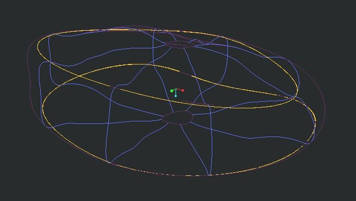
Here is the wireframe view of the above model.
Please, help!
This thread is inactive and closed by the PTC Community Management Team. If you would like to provide a reply and re-open this thread, please notify the moderator and reference the thread. You may also use "Start a topic" button to ask a new question. Please be sure to include what version of the PTC product you are using so another community member knowledgeable about your version may be able to assist.
Solved! Go to Solution.
Labels:
- Labels:
-
2D Drawing
ACCEPTED SOLUTION
Accepted Solutions
Dec 10, 2014
02:06 AM
- Mark as New
- Bookmark
- Subscribe
- Mute
- Subscribe to RSS Feed
- Permalink
- Notify Moderator
Please log in to access translation
Dec 10, 2014
02:06 AM
Well, I did say it was a trick; not necessarily a solution.
However, by the same token, you can place a datum point in the middle of the hole and do the same thing.
Add tangency at the edges of the bounding surface and put a pin in it.
The point can be located by drawing a datum curve between two opposite vertices. Then place a point at 0.5 ratio along the curve. If you don't like the 1st result, you can tweak the points location or the shape of the datum curve, which also can be managed with tangency.
23 REPLIES 23
Dec 09, 2014
05:01 AM
- Mark as New
- Bookmark
- Subscribe
- Mute
- Subscribe to RSS Feed
- Permalink
- Notify Moderator
Please log in to access translation
Dec 09, 2014
05:01 AM
Hi,
I guess that there are no real gaps in your model. Your model consists of 3 separate quilts. To be able to solidify the model, you have to merge 3 quilts into 1. Simply select two quilts and apply Merge command. You will need 2 Merge features to get the requested quilt.
Martin Hanak
Martin Hanák
Dec 09, 2014
09:40 PM
- Mark as New
- Bookmark
- Subscribe
- Mute
- Subscribe to RSS Feed
- Permalink
- Notify Moderator
Please log in to access translation
Dec 09, 2014
09:40 PM
Hi Martin,
Thank for your enlightenment. I manage to merge to bottom-to-wall quilt. But when I merge the top-to-wall quilt, the top surface was deleted.
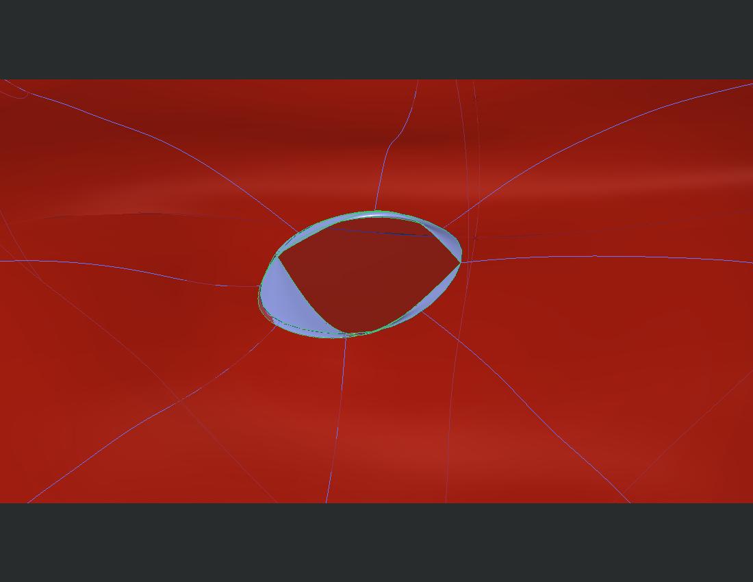
Zoomed up image of the top-to-wall boundary is as below:
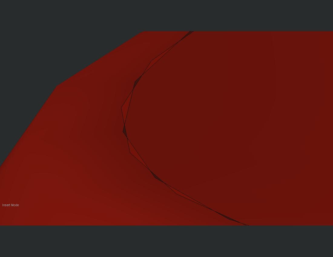
Seems like some area are intersecting, while some other area are the gap. Tried the trim command, but doesn't change the end result. 
Dec 10, 2014
03:07 AM
- Mark as New
- Bookmark
- Subscribe
- Mute
- Subscribe to RSS Feed
- Permalink
- Notify Moderator
Please log in to access translation
Dec 10, 2014
03:07 AM
Hi,
- Merge command has two options - Intersect and Join. Did you try both of them ? There are "arrow", which enable to change side to be included in the merge
- Did the second Merge fail ?
- maybe you can redefine TOP quilt and use WALL boundary edge as reference instead of datum curve
Martin Hanak
Martin Hanák
Dec 10, 2014
03:36 AM
- Mark as New
- Bookmark
- Subscribe
- Mute
- Subscribe to RSS Feed
- Permalink
- Notify Moderator
Please log in to access translation
Dec 10, 2014
03:36 AM
Yeah, the Merge failed during the first try. It suggest to try the trim/extend command..
So I redefine a new curve as the reference boundary point for of the wall and top+bottom surface -- and it works just as I wanted! Thanks! 
Dec 09, 2014
09:36 AM
- Mark as New
- Bookmark
- Subscribe
- Mute
- Subscribe to RSS Feed
- Permalink
- Notify Moderator
Please log in to access translation
Dec 09, 2014
09:36 AM
What is it, a bean bag chair?
Dec 09, 2014
09:41 PM
- Mark as New
- Bookmark
- Subscribe
- Mute
- Subscribe to RSS Feed
- Permalink
- Notify Moderator
Please log in to access translation
Dec 09, 2014
09:41 PM
Just to answer your curiosity. it's the disc in between the vertebral bone.
Dec 09, 2014
10:55 PM
- Mark as New
- Bookmark
- Subscribe
- Mute
- Subscribe to RSS Feed
- Permalink
- Notify Moderator
Please log in to access translation
Dec 09, 2014
10:55 PM
I find playing with irregular surfaces absolutely frustrating in Creo.
What I normally end up doing is going after it in many different ways up to and including manipulating the default import features by changing the defaults prior to the import being done. It seems to heal a few issues but not much. In general, the export will come back the same or worse.
I think in your case, the technique is in the creation of the boundary blends and style features. You probably don't need the style feature in this case.
Can you post the model just before the merge function to see what others can do with this? Also state what version you are using... Creo 2.0, 3.0, or academic, trial, all change what people can do with it. An IGES and STEP export will be somewhat universal.
And the graphic "disconnects" may be just that, graphic artifacts. Creo is very particular about which edges you use to create things that are intended for merge.
It took years but I finally got IDD to zip up some edges... and I am beginning to understand some of it geometry error messages and how to resolve the. Again... not one solution, but many to try.
Dec 09, 2014
11:32 PM
- Mark as New
- Bookmark
- Subscribe
- Mute
- Subscribe to RSS Feed
- Permalink
- Notify Moderator
Please log in to access translation
Dec 09, 2014
11:32 PM
Hi,
Ok, so I manage to improve the surface features by redefining the boundary curve between top-wall-bottom surface. It seems to work as I wanted using boundary blend command..
BUT, now, the glitch is -- there's a real hole in my model which I cannot fill. Tried to fill it with the command below:
- fill
- style (I keep re-adjusting the sequence of boundary line chosen)
- boundary blend
without much success.. 
Here's the link to the STEP file. I'm currently using Ceo Parametric 3.0 student version.
https://grabcad.com/library/intervertebral-disc-1/files/141210_ivd_L4L5.stp
Dec 11, 2014
12:57 AM
- Mark as New
- Bookmark
- Subscribe
- Mute
- Subscribe to RSS Feed
- Permalink
- Notify Moderator
Please log in to access translation
Dec 11, 2014
12:57 AM
Hi,
to upload STEP file to communities.ptc.com, click Use advanced editor link (top right corner of Reply window) and use Browse command located at the bottom side of text area (I do not want to create Grabcad account).
I guess that you have solid model in Creo Parametric 3.0 Student version and when you export it into STEP and reimport it into Creo, it contains gaps.
Is it true ?
Why do you export STEP file ?
Did you try other export formats ?
Martin Hanak
Martin Hanák
Dec 11, 2014
06:19 AM
- Mark as New
- Bookmark
- Subscribe
- Mute
- Subscribe to RSS Feed
- Permalink
- Notify Moderator
Please log in to access translation
Dec 11, 2014
06:19 AM
I asked Masni to export the step, Martin. But like you, I also have no desire to create yet another account. And since the issue is solved, no worries
Dec 09, 2014
11:00 PM
- Mark as New
- Bookmark
- Subscribe
- Mute
- Subscribe to RSS Feed
- Permalink
- Notify Moderator
Please log in to access translation
Dec 09, 2014
11:00 PM
Where's the hole?
Dec 09, 2014
11:33 PM
- Mark as New
- Bookmark
- Subscribe
- Mute
- Subscribe to RSS Feed
- Permalink
- Notify Moderator
Please log in to access translation
Dec 09, 2014
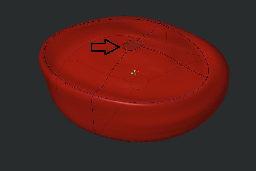
11:33 PM
After much readjustin and modifying, here's the HOLE~
Dec 09, 2014
11:58 PM
- Mark as New
- Bookmark
- Subscribe
- Mute
- Subscribe to RSS Feed
- Permalink
- Notify Moderator
Please log in to access translation
Dec 09, 2014
11:58 PM
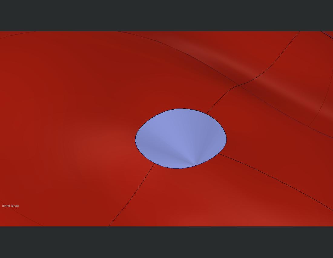
Interesting trick for holes. Use a boundary blend and select a vertex as the 1st feature, and the entire edge as the second feature. This draws all the edges to a single point.
Dec 10, 2014
01:40 AM
- Mark as New
- Bookmark
- Subscribe
- Mute
- Subscribe to RSS Feed
- Permalink
- Notify Moderator
Please log in to access translation
Dec 10, 2014
01:40 AM
Ok, this is new.
So I tried selecting a point (tried at multiple location) and the edge for boundary blend feature. The following image are the result.
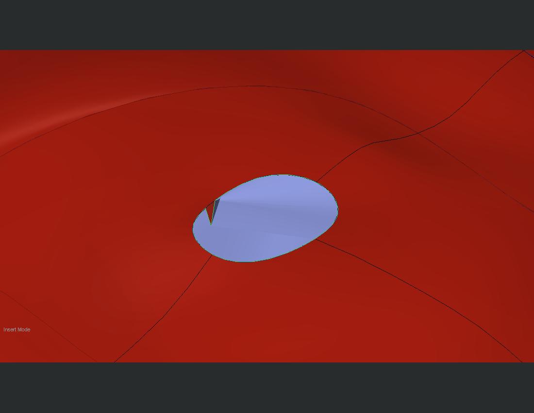
Not the profile I wanted.
Close to what I need, but the warping at the point is really bugging.. Any way to make it a smooth surface?
Tested for multiple points. Nope, not the output needed..
Dec 10, 2014
01:50 AM
- Mark as New
- Bookmark
- Subscribe
- Mute
- Subscribe to RSS Feed
- Permalink
- Notify Moderator
Please log in to access translation
Dec 10, 2014
01:50 AM
If a vertex is selected like that it will pinch as it's a singularlity. It may smooth out using tangency references. Worst case, copy the curve twice and trim them so they form two halves, then blend between them.
Dec 10, 2014
02:06 AM
- Mark as New
- Bookmark
- Subscribe
- Mute
- Subscribe to RSS Feed
- Permalink
- Notify Moderator
Please log in to access translation
Dec 10, 2014
02:06 AM
Well, I did say it was a trick; not necessarily a solution.
However, by the same token, you can place a datum point in the middle of the hole and do the same thing.
Add tangency at the edges of the bounding surface and put a pin in it.
The point can be located by drawing a datum curve between two opposite vertices. Then place a point at 0.5 ratio along the curve. If you don't like the 1st result, you can tweak the points location or the shape of the datum curve, which also can be managed with tangency.
Dec 10, 2014
03:31 AM
- Mark as New
- Bookmark
- Subscribe
- Mute
- Subscribe to RSS Feed
- Permalink
- Notify Moderator
Please log in to access translation
Dec 10, 2014
03:31 AM
Hey thanks... Finally I manage to fill the gaps using the combination of all your suggestions! Great!
Danke schon!
Dec 10, 2014
02:08 AM
- Mark as New
- Bookmark
- Subscribe
- Mute
- Subscribe to RSS Feed
- Permalink
- Notify Moderator
Please log in to access translation
Dec 10, 2014
02:08 AM
Dec 10, 2014
03:29 AM
- Mark as New
- Bookmark
- Subscribe
- Mute
- Subscribe to RSS Feed
- Permalink
- Notify Moderator
Please log in to access translation
Dec 10, 2014
03:29 AM
Love this..I wish we had some Dicom image in our laboratory.. At the time being, we just have to make do with the CT-slice images.
Dec 10, 2014
11:22 AM
- Mark as New
- Bookmark
- Subscribe
- Mute
- Subscribe to RSS Feed
- Permalink
- Notify Moderator
Please log in to access translation
Dec 10, 2014
11:22 AM
On that one, try using an n-sided surf.
Dec 10, 2014
01:41 AM
- Mark as New
- Bookmark
- Subscribe
- Mute
- Subscribe to RSS Feed
- Permalink
- Notify Moderator
Please log in to access translation
Dec 10, 2014
01:41 AM
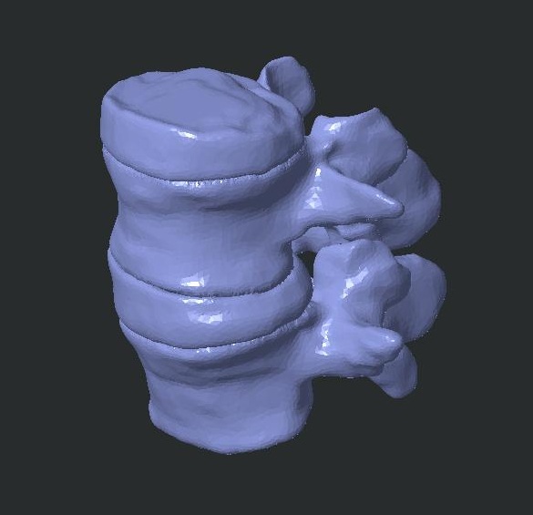
I meant in the picture you had of the disks and vertebrae. It looked like the nucleous pulposus is indistinct. A vertebral disk is an interesting composite structure with the oriented fibers of the annulus containing the internal pressure of the nucleous.
The model looks interesting. What's the model going to be used for?
Dec 10, 2014
03:27 AM
- Mark as New
- Bookmark
- Subscribe
- Mute
- Subscribe to RSS Feed
- Permalink
- Notify Moderator
Please log in to access translation
Dec 10, 2014
03:27 AM
Haha! Sorry for the misunderstanding.
Yeah, it is an interesting and tricky structure. It is actually for some disc degeneration study my professor asked us to explore. We couldn't trace out the anulus fibrosus and the nucleus pulposus region from the CT scan image. So, we segmented the external profiles, and constructed the distinction of the outer + inner AF with NP with Creo to generate the region that we needed to allow us to assign the material properties for respective region.
Hope I am going at the right direction~
Dec 10, 2014
11:24 AM
- Mark as New
- Bookmark
- Subscribe
- Mute
- Subscribe to RSS Feed
- Permalink
- Notify Moderator
Please log in to access translation
Dec 10, 2014
11:24 AM
Cool! I'm in the medical field myself.


