
Turn on suggestions
Auto-suggest helps you quickly narrow down your search results by suggesting possible matches as you type.
Showing results for
Please log in to access translation
Turn on suggestions
Auto-suggest helps you quickly narrow down your search results by suggesting possible matches as you type.
Showing results for
Community Tip - Visit the PTCooler (the community lounge) to get to know your fellow community members and check out some of Dale's Friday Humor posts! X
- Community
- Creo+ and Creo Parametric
- 3D Part & Assembly Design
- Re: Fix displacement in only +ve direction for non...
Translate the entire conversation x
Please log in to access translation
Options
- Subscribe to RSS Feed
- Mark Topic as New
- Mark Topic as Read
- Float this Topic for Current User
- Bookmark
- Subscribe
- Mute
- Printer Friendly Page
Fix displacement in only +ve direction for non-linear analysis?
Oct 07, 2014
03:00 AM
- Mark as New
- Bookmark
- Subscribe
- Mute
- Subscribe to RSS Feed
- Permalink
- Notify Moderator
Please log in to access translation
Oct 07, 2014
03:00 AM
Fix displacement in only +ve direction for non-linear analysis?
Hello,
I am performing non-linear static analysis and have the following 2 questions:
1. I want to constrain a surface such that it is not allowed to move in the +Z direction but free to move in the -Z direction.
Z is normal to the surface.
2. Secondly I want to know whether the displacement can be made a function of time similar to loads?
Solved! Go to Solution.
Labels:
- Labels:
-
Surfacing
ACCEPTED SOLUTION
Accepted Solutions
Oct 19, 2014
06:06 PM
- Mark as New
- Bookmark
- Subscribe
- Mute
- Subscribe to RSS Feed
- Permalink
- Notify Moderator
Please log in to access translation
Oct 19, 2014
06:06 PM
I'm a little confused on what your analysis setup is suppose to be for the assembly level or what the goals of the analysis are (stress, displacement, etc.). Could you put something together describing the real-world problem you're trying to simulate and what you want to capture.
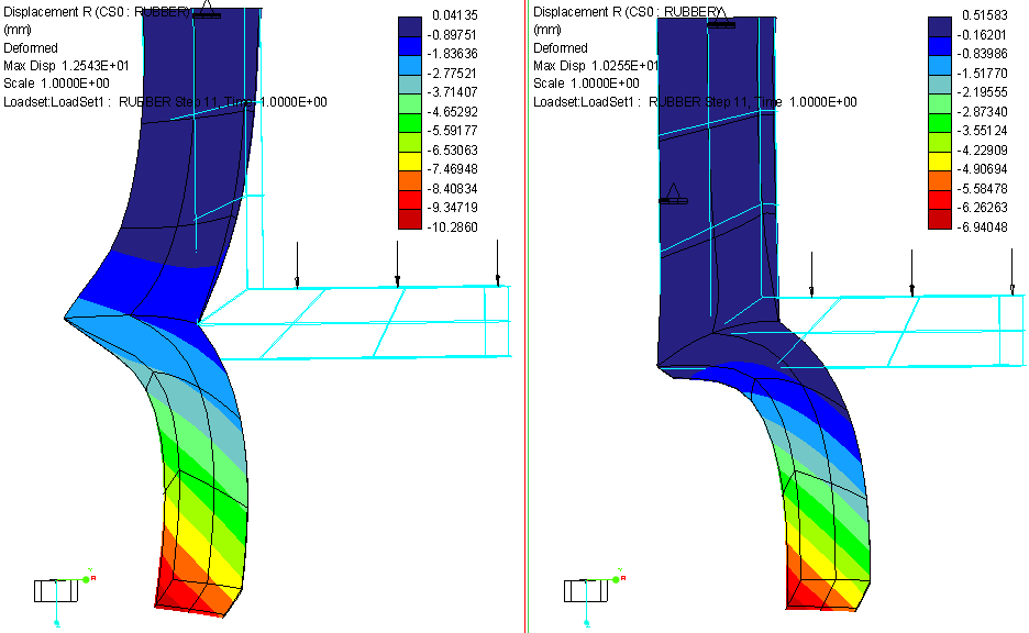
For your part level analysis, part of the reason why your analysis took so long to run is that you're having numerical stability issues. If you look in the .PAS file, you'll see several pseudo time steps are taking 100-150 iterative steps to convergence on an acceptable residual nor level, and on a couple different occasions your stiffness matrix becomes singular. If you look at the first pass results, you'll see that the outer most tip of the flange displaces more that its radius; this means that you applied load is now going to be a (mostly) shear load on the surface. This in combination with the very large displacements you're having is part of the reason why the analysis is taking so long to run.
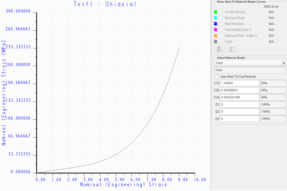
Now, if you want to try to approximate a contact surface between the inner curved surface of the rubber part, then you could create a cylindrical coordinate system and constrain the surface in the radial direction (but remember, the surface will not be able to move in the + or - R direction). Looking at the stress-strain curve for your hyperelastic material models makes me think that this assumption isn't too bad. From a strain of 0 to 5 your stress increases by about 30 MPa, giving a linearized Young's Modulus of about 6 MPa; after that, the next linearized Young's Modulus would be about 50 MPa. Your base material has a Young's Modulus of 7 GPa, so we have about 2-3 orders of magnitude greater stiffness on the base. You can see how this helps reduce the displacements, but you will have the flange deformed to a vertical position. At this position do you really expect to have a 10 N load vertically down (which, for the deformed shape, would be something like a friction load).
12 REPLIES 12
Oct 07, 2014
03:05 PM
- Mark as New
- Bookmark
- Subscribe
- Mute
- Subscribe to RSS Feed
- Permalink
- Notify Moderator
Please log in to access translation
Oct 07, 2014
03:05 PM
I want to constrain a surface such that it is not allowed to move in the +Z direction but free to move in the -Z direction.
You're not going to be able to do this directly. What you're describing is a contact conditions (stiffness is unit-vector dependent); a constraint is specifying the displacements (knowns and unknows) for points/edges/surfaces on the element(s) and it's something that you won't be able to "turn-off".
Secondly I want to know whether the displacement can be made a function of time similar to loads?
You can make enforced displacements a function of pseudo-time; this is done by clicking the "f(x)" button under "Time Dependent" in the constraint box (you'll see "Ramp" next to "f(x)" by default). Keep in mind that the y-value of your function/table defines the scalar value of the enforced displacement. If you have an enforced displacement value of 3e-3 in, then when the time-dependent function/table has a y-value of 1, the value of the enforced displacement will be 3e-3 in (likewise, a y-value of 2 will be an enforced displacement value of 6e-3 in).
Oct 16, 2014
07:58 AM
- Mark as New
- Bookmark
- Subscribe
- Mute
- Subscribe to RSS Feed
- Permalink
- Notify Moderator
Please log in to access translation
Oct 16, 2014
07:58 AM
Hi Shaun,
I appologise for the delay as I was out of office until today.
1. I dont think this constraint will define the displacement of the nodes, it will only limit the displacement in one direction. All other DOFs are free. Additionally, the planar constraint is quite apposite for this task. But I am unable to comprehend why it is allowed only for SDA and not for LDA.
2. What you say is correct, but that is not what I require. I want to fix some of the DOFs of some nodes for a specified time interval and for the remaining time interval these DOFs are free and unconstrained. I tried to make the displacement constraint a function of time, but it has no effect, which seems logical considering displacement constraint makes displacement zero and plotting a graph of displacement vs time is irrelevant as 0 X anything(value from graph) = 0. So eventually the fix displacement will apply for the entire time interval. Thus Simulate does not allow such situation to be simulated, however it is a perfectly valid situation and could be supported in future releases. What do you say?
Oct 16, 2014
10:30 PM
- Mark as New
- Bookmark
- Subscribe
- Mute
- Subscribe to RSS Feed
- Permalink
- Notify Moderator
Please log in to access translation
Oct 16, 2014
10:30 PM
1. I dont think this constraint will define the displacement of the nodes, it will only limit the displacement in one direction. All other DOFs are free. Additionally, the planar constraint is quite apposite for this task. But I am unable to comprehend why it is allowed only for SDA and not for LDA.
A constraint is, by definition, a prescribed nodal displacement. All static structural problems involve solving:
{f} = [k]{d}
where {f} defines the forces acting on the system, [k] defines the stiffness matrix of the system, and {d} defines the nodal displacements. Your constraints define your displacement vector {d}; i.e. a "fixed" constraint on a surface defines all nodal displacements (Tx, Ty, Tz, and Rx, Ry, Rz if the element type has rotational DOF) on that surface to be 0. Nodes that have no constraints applied to them are unknowns that need to be solved for. You need to also keep in mind that there are only 6 DOF total (translations in x, y, and z, and rotations in x, y, and z), so there is no way to prevent a node from moving in the -x direction while still allowing it to move in the +x direction. That type of requirement is typically handled via contact, not with a constraint. If you want to prevent a surface from moving in (for example) the -x direction but allowing it to move in the +x direction, you'll need to either create a wall and define a contact set between it and the other part, or use non-linear springs (this may or may not work or be realistic depending on what you're modeling and what you need from a results standpoint).
2. What you say is correct, but that is not what I require. I want to fix some of the DOFs of some nodes for a specified time interval and for the remaining time interval these DOFs are free and unconstrained. I tried to make the displacement constraint a function of time, but it has no effect, which seems logical considering displacement constraint makes displacement zero and plotting a graph of displacement vs time is irrelevant as 0 X anything(value from graph) = 0. So eventually the fix displacement will apply for the entire time interval. Thus Simulate does not allow such situation to be simulated, however it is a perfectly valid situation and could be supported in future releases. What do you say?
You're correct: Simulate doesn't allow the user to "turn-off" a constraint during a simulation. While it is a perfectly valid simulation, there might be a technical reason why Simulate doesn't have this feature (or maybe it's not high on PTC's list of Things-To-Do). That being said, there are potential work-around's that may or may not work for your model (I'd need to understand your model to know one way or the other) that involve time-dependent loads and springs.
Oct 19, 2014
02:36 AM
- Mark as New
- Bookmark
- Subscribe
- Mute
- Subscribe to RSS Feed
- Permalink
- Notify Moderator
Please log in to access translation
Oct 19, 2014
02:36 AM
Hello Shaun,
I have uploaded a simplified version of my scenario.
Can you see my reply to Steven below?
Oct 13, 2014
12:54 PM
- Mark as New
- Bookmark
- Subscribe
- Mute
- Subscribe to RSS Feed
- Permalink
- Notify Moderator
Please log in to access translation
Oct 13, 2014
12:54 PM
Hello Sumit,
did the hints from Steven and Shaun help you?
Gunter
Oct 16, 2014
08:00 AM
- Mark as New
- Bookmark
- Subscribe
- Mute
- Subscribe to RSS Feed
- Permalink
- Notify Moderator
Please log in to access translation
Oct 16, 2014
08:00 AM
Hello Gunter,
As mentioned previously I was out of office until today and I appologise for the delay in reply.
I am not yet satisfied with the suggestions and am looking forward to further refinement.
Oct 19, 2014
02:35 AM
- Mark as New
- Bookmark
- Subscribe
- Mute
- Subscribe to RSS Feed
- Permalink
- Notify Moderator
Please log in to access translation
Oct 19, 2014
02:35 AM
Hello Steven,
I have uploaded a simplified model similar to my requirement.
http://communities.ptc.com/servlet/JiveServlet/downloadBody/6419-102-1-9748/17.10.2014.zip
The contact analysis in my case is taking tremendous time, so I wanted to run an equivalent simulation only on the rubber part.
Let me know which set of constraints could approximately give similar results as the contact analysis?
Oct 19, 2014
06:06 PM
- Mark as New
- Bookmark
- Subscribe
- Mute
- Subscribe to RSS Feed
- Permalink
- Notify Moderator
Please log in to access translation
Oct 19, 2014
06:06 PM
I'm a little confused on what your analysis setup is suppose to be for the assembly level or what the goals of the analysis are (stress, displacement, etc.). Could you put something together describing the real-world problem you're trying to simulate and what you want to capture.
For your part level analysis, part of the reason why your analysis took so long to run is that you're having numerical stability issues. If you look in the .PAS file, you'll see several pseudo time steps are taking 100-150 iterative steps to convergence on an acceptable residual nor level, and on a couple different occasions your stiffness matrix becomes singular. If you look at the first pass results, you'll see that the outer most tip of the flange displaces more that its radius; this means that you applied load is now going to be a (mostly) shear load on the surface. This in combination with the very large displacements you're having is part of the reason why the analysis is taking so long to run.
Now, if you want to try to approximate a contact surface between the inner curved surface of the rubber part, then you could create a cylindrical coordinate system and constrain the surface in the radial direction (but remember, the surface will not be able to move in the + or - R direction). Looking at the stress-strain curve for your hyperelastic material models makes me think that this assumption isn't too bad. From a strain of 0 to 5 your stress increases by about 30 MPa, giving a linearized Young's Modulus of about 6 MPa; after that, the next linearized Young's Modulus would be about 50 MPa. Your base material has a Young's Modulus of 7 GPa, so we have about 2-3 orders of magnitude greater stiffness on the base. You can see how this helps reduce the displacements, but you will have the flange deformed to a vertical position. At this position do you really expect to have a 10 N load vertically down (which, for the deformed shape, would be something like a friction load).
Oct 26, 2014
11:36 PM
- Mark as New
- Bookmark
- Subscribe
- Mute
- Subscribe to RSS Feed
- Permalink
- Notify Moderator
Please log in to access translation
Oct 26, 2014
11:36 PM
Could you put something together describing the real-world problem you're trying to simulate and what you want to capture.
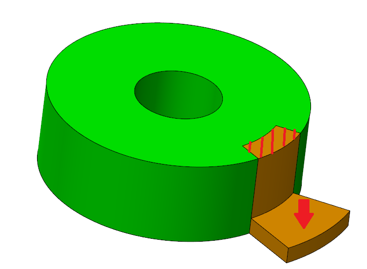
The hatched surface of rubber (yellow) is fixed to the base (green) by adhesives (Actually it is much more complicated than that, but for simplicity please assume this).
The arrow shows the force applied on rubber surface to pull it outside of base.
The assembly file I uploaded is a simplified version of our product that I created quickly.
Ignore the assembly constraints, the purpose was only to show you how the interface between the parts is.
You can open the rubber part and then open Simulate, it will show the constraints applied by me.
As you will understand immediately, it is a very crude approximation of the situation and I want to refine it further.
In our actual product the contact interface is much more complicated, hence the contact analysis is not feasible. That is why I want to run an equivalent analysis only on the rubber part.
If you look at the first pass results, you'll see that the outer most tip of the flange displaces more that its radius
This is because the constraint set is incomplete; there is no constraint on the contact area of the rubber i.e. the rubber cannot go in the direction of its centre (same as centre axis of base part) as base part is already present there and it is considered undeformable. So the rubber should be allowed to displace away from the centre but not towards the centre. How do I apply constraints to achieve this?
For your part level analysis, part of the reason why your analysis took so long to run is that you're having numerical stability issues
This should be normal for the p method right?
Since the equations are solved in itterations until appreciable continuity is achieved, this behaviour is as expected IMHO.
Now, if you want to try to approximate a contact surface between the inner curved surface of the rubber part, then you could create a cylindrical coordinate system and constrain the surface in the radial direction (but remember, the surface will not be able to move in the + or - R direction)
Yes you got it exactly right over here. I want to constrain the surface to not move in -R direction but free to move in +R direction. But as you say it is not possible in Simulate. So any other alternatives for my boundary conditions?
I dont know why your graph is like that. Maybe because of difference in units?
At this position do you really expect to have a 10 N load vertically down (which, for the deformed shape, would be something like a friction load)
The rubber part is very flexible. The load is actually applied by fingers, so the fingers can adjust accordingly to pull the rubber part out of the base.
Oct 27, 2014
04:06 PM
- Mark as New
- Bookmark
- Subscribe
- Mute
- Subscribe to RSS Feed
- Permalink
- Notify Moderator
Please log in to access translation
Oct 27, 2014
04:06 PM
...as base part is already present there and it is considered undeformable.
If you're comfortable with this assumption, then the radial constraint I used is a good approximation (based on your loading condition).
So the rubber should be allowed to displace away from the centre but not towards the centre. How do I apply constraints to achieve this?
Again, you cannot do this with a constraint; a constraint defines the displacement values of the nodes it's applied to (i.e. the DOFs for the nodes being constrained go from unknowns to knowns).
This should be normal for the p method right? Since the equations are solved in itterations until appreciable continuity is achieved, this behaviour is as expected IMHO.
This isn't specific to the p-method; you'd see this issue in a h-method code. The iterative nature of the analysis is because it's non-linear; the solver iterating until an acceptable residual norm is achieved is just part of Newton's Method. That being said, research has shown that the p-method is better at minimizing the accumulation of error over the multiple load steps in a non-linear analysis, but the reason for this isn't related to what you're experiencing.
Yes you got it exactly right over here. I want to constrain the surface to not move in -R direction but free to move in +R direction. But as you say it is not possible in Simulate. So any other alternatives for my boundary conditions?
You could add in a small sub-section of your base and define a contact interface; you also might be able to use non-linear springs (in place of the sub-section of your base part), but there could be some caveats to this (I'd have to think about it some more). However, based on your loading condition and that you're considering the base par to be undeformable, why don't you want to use the radial constraint? Are there additional loads that, when added, will want to pull the flange away from the base?
I also want to point out that a large-displacement/strain formulation with contact is something that is rather new to Simulate, and as such, isn't the most robust; it can be very difficult to get the two to work together properly.
I dont know why your graph is like that. Maybe because of difference in units?
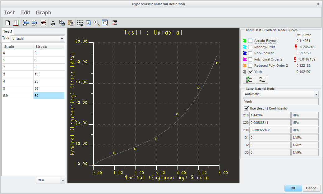
No, the units are the same (MPa). It looks like there is a difference because mine covers a larger strain and stress range. I generated my graph by taking the material coefficients (C10, C20, C30, and D1-3) for your Yeoh material model, which is what your model is doing as well (it takes the strain-strain points you've defined, fitted a Yeoh material model to them, and then uses that Yeoh model for the analysis itself).
The rubber part is very flexible. The load is actually applied by fingers, so the fingers can adjust accordingly to pull the rubber part out of the base.
Do you have a defined loading condition for this? Such as magnitude and direction (and how they vary with time)?
Oct 27, 2014
11:32 PM
- Mark as New
- Bookmark
- Subscribe
- Mute
- Subscribe to RSS Feed
- Permalink
- Notify Moderator
Please log in to access translation
Oct 27, 2014
11:32 PM
If you're comfortable with this assumption, then the radial constraint I used is a good approximation (based on your loading condition)
I agree that it could be the best possible approximation using Simulate. But do you think that some other softwares like Abaqus, ANSYS could have this unidirectional constraint ability? Maybe this could be achieved by bettter algorithms?
but the reason for this isn't related to what you're experiencing.
Usually I experience these multiple steps for each time step for most of my analyses i.e. say there will be 50 steps for time 0.1S then there will be 50 more steps for time 0.2S. Am I doing something wrong?
why don't you want to use the radial constraint? Are there additional loads that, when added, will want to pull the flange away from the base?
Actually the problem is much more complicated than I said previously. There are 2 considerations:
1. The portion of the rubber in contact with base should be allowed to move in +R direction but not in -R direction UNTIL the rubber is in contact with base. When the rubber is displacing down, after some time it will no longer be in contact with the base (see the assembly to understand this). So after this time the constraints should be that the rubber surface is allowed to move in +R as well as -R directions. To clarify better:
- if (rubber node is in contact with base surface) allow rubber node in +R but not in -R
- else allow rubber node in +R as well as -R
Now as you said this -R only constraint does not exist in Simulate.
Additionally Simulate does not allow time varying boundary conditions.
So all in all, my actual scenario is impossible to simulate in Simulate.
2. If we apply the radial constraint as suggested by you, the result is
- if (rubber node is in contact with base surface) do not allow -R (ok) and +R(not ok) movements
- else do not allow movement in -R(not ok) and +R(not ok)
As you can see the results are not what is desired.
3. If you refer the model that I uploaded, it does not have the radial constraint. So the result is:
- if (rubber node is in contact with base surface) allow +R (ok) and -R (not ok) movements
- else allow movement in -R (ok) and +R (ok) movements
I know that it is quite confusing... 
Do you have a defined loading condition for this? Such as magnitude and direction (and how they vary with time)?
No, not yet. I am sort of reverse engineering the physical results into the software to learn Simulate.
But till what I have reached, initially there is only vertical load until time 0.5S. Then there is addition of a horizontal load for time 0.5 to 1S along with the vertical load. The problem is that the load will adjust as per the deformation of the rubber and I am not able to simulate that properly as of now. It depends on how approximate my BCs are...
Oct 28, 2014
03:12 PM
- Mark as New
- Bookmark
- Subscribe
- Mute
- Subscribe to RSS Feed
- Permalink
- Notify Moderator
Please log in to access translation
Oct 28, 2014
03:12 PM
I agree that it could be the best possible approximation using Simulate. But do you think that some other softwares like Abaqus, ANSYS could have this unidirectional constraint ability? Maybe this could be achieved by bettter algorithms?
I'm not too familiar with either of those packages to say definitively whether or not they have a direction dependent constraint, but I do know that they (ANSYS, Abaqus, etc.) support rigid virtual walls (which you could define a contact set with your part).
Usually I experience these multiple steps for each time step for most of my analyses i.e. say there will be 50 steps for time 0.1S then there will be 50 more steps for time 0.2S. Am I doing something wrong?
Depends. When you say, "there will be 50 more steps", are these load steps, or iterations? Are these the steps you're talking about?
Iteration Residual norm
------------- -------------
1 0.5 Mon Oct 27, 2014 14:53:58
2 0.000168035 Mon Oct 27, 2014 14:53:58
3 9.66176e-007 Mon Oct 27, 2014 14:53:59
4 2.80372e-008 Mon Oct 27, 2014 14:53:59
5 7.09408e-011 Mon Oct 27, 2014 14:54:00
6 1.466e-012 Mon Oct 27, 2014 14:54:01
7 8.06062e-016 Mon Oct 27, 2014 14:54:01
If you're seeing the above, then it's most likely not an issue; these are the iterative steps associated with Newton's Method. There is not hard and fast correct number of iterative steps; how many steps it takes depends on the non-linear nature of the problem, your mesh, and your load step size. If you're seeing a message about the load factor being decreased, then there are probably some issues with your model/setup.
Actually the problem is much more complicated than I said previously...
In that case, it'd be best to model a sub-section of the base and define a contact interface.
But till what I have reached, initially there is only vertical load until time 0.5S. Then there is addition of a horizontal load for time 0.5 to 1S along with the vertical load. The problem is that the load will adjust as per the deformation of the rubber and I am not able to simulate that properly as of now. It depends on how approximate my BCs are...
You might be able to do this in Simulate; I can't say for sure until I get a better idea of the exact nature of the loading conditions. That being said, keep in mind that a force load is always relative to the initial geometry, whereas a pressure load is with respect to the current geometry (hence pressure loads sometimes being referred to as 'follower loads'). There are different methods for adjusting both pressure and force loads to mimic loads that vary in magnitude and direction as a function of pseudo time.


