Community Tip - Did you get called away in the middle of writing a post? Don't worry you can find your unfinished post later in the Drafts section of your profile page. X
- Community
- Creo+ and Creo Parametric
- 3D Part & Assembly Design
- Re: Flexible hose for Reuse in multiple different ...
- Subscribe to RSS Feed
- Mark Topic as New
- Mark Topic as Read
- Float this Topic for Current User
- Bookmark
- Subscribe
- Mute
- Printer Friendly Page
Flexible hose for Reuse in multiple different assemblies - solution for simple case.
- Mark as New
- Bookmark
- Subscribe
- Mute
- Subscribe to RSS Feed
- Permalink
- Notify Moderator
Flexible hose for Reuse in multiple different assemblies - solution for simple case.
If you look how to create simple flex hose so that it could be reused in multiple assemblies of different geometry – this is for you.
Please note, that proposed technique will fit only for cases when flexible hose goes port – to – port and does not have intermediate points that need to snap to geometry i.e. most simple case. It actually can have internal routing points but only so that they are defined relative to connectors and do not have to snap outside.
Solution uses existing Creo capabilities in flexible components and mechanism general connections (will work even in Wildfire), and its main purpose is to avoid standard flex hose assembly modification while stitched to yet another place. Below come pictures and explanations.
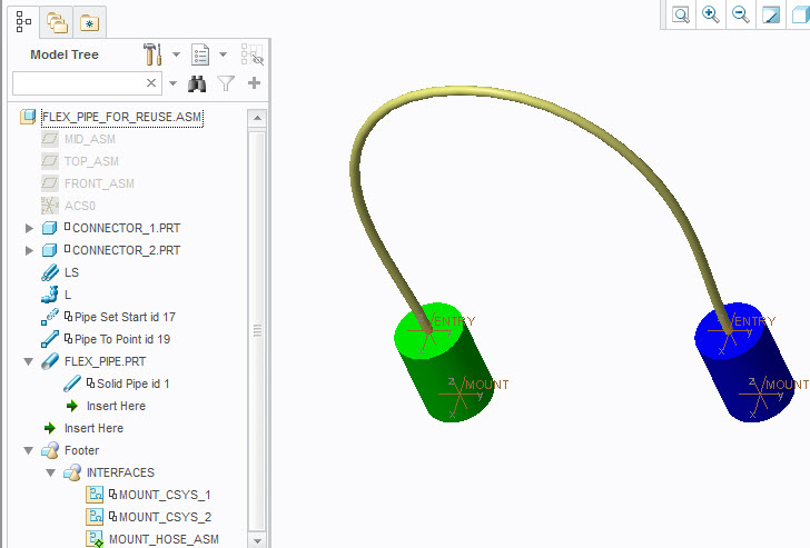
- General view of resulting assembly with flex hose :
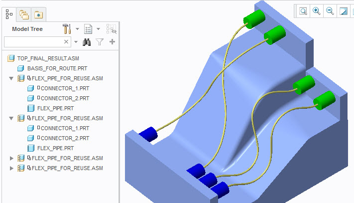
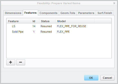
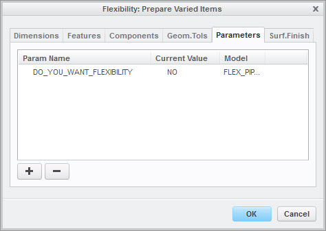
- Flexibility definition inside flex pipe assembly (FLEX_PIPE_FOR_REUSE.ASM in attached example) :
In order for assembly to be fully flexible and never modify the original one, add following features into Model Properties / Flexibility : Line stock (from assembly) and Solid Pipe (from solid pipe, if you create it). Also prepare assembly level parameter called DO_YOU_WANT_FLEXIBILITY = Yes / No*.
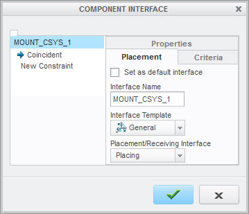
- Interfaces preparation on flex pipe assembly level (can be skipped, but makes life very simple):
- MOUNT_CSYS_1 interface of General Connection type, Coincident, select CONNECTOR_1 mounting CSYS. Interface should be of “placing” type.
- MOUNT_CSYS_2 interface of General Connection type, Coincident, select CONNECTOR_2 mounting CSYS. Interface should be of “placing” type.
- MOUNT_HOSE_ASM - combined interface that includes both previous ones, of “user defined / placing” type
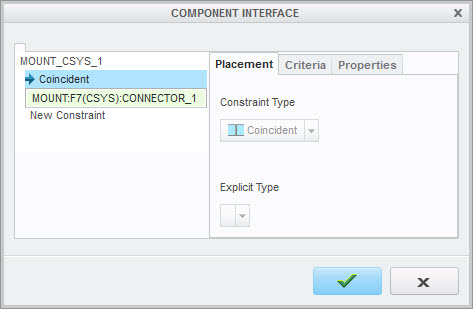
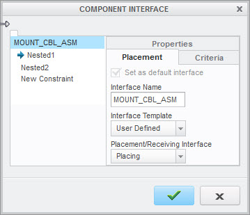
- Other specifics in flex hose assembly (see picture below) :
- Both connectors should be places as fully packaged – no constraints at all. This is critical for the workflow to succeed.
- Fixed length can be used over the hose, if desired.
- Upon placing flex hose assembly into top assembly, confirm “yes” to use flexibility and in flexible varied items dialogue change parameter DO_YOU_WANT_FLEXIBILITY = Yes , and then OK. Ensure that your placement shows “Interface to Geometry” and select respective 2 coordinate systems to locate flex hose assembly. Confirm placement and then regenerate – hose will update its location as required.


- Now same hose can be placed as many times as needed to different locations, and will always adopt to each occurrence respective geometry. It can be multiplied also by Component Repeat, Copy – Paste Special (new references) and any other existing way. At any of these, original assembly is not modified. Enjoy attached movie for entire workflow.
As mentioned above, having more routing points inside flex hose assembly is possible if they are all created respective “internal references” in the same assembly. Having external references for routing points that each time will need to snap to another outer assembly geometry is a problem and not supported in current solution.
There is a way to do so, but it is more complicated and loses the simplicity of this solution.
So this is NOT a “full blown” flexible hose solution yet.
Hope you found this useful, any related questions and comments are appreciated.
Regards
- Vlad
- Mark as New
- Bookmark
- Subscribe
- Mute
- Subscribe to RSS Feed
- Permalink
- Notify Moderator
Just in case anyone tried this out, any feedback / comments are appressiated.
We are indeed interesetd to see if it serves the needs, if yes then to what extent and what are the main gaps remaining in your use cases.
- Mark as New
- Bookmark
- Subscribe
- Mute
- Subscribe to RSS Feed
- Permalink
- Notify Moderator
Vkad,
I see this only practical if I have a very simple routing where I don't care what the path of the house is. What if I need to change/tweak the path in between to route through or around something?
- Mark as New
- Bookmark
- Subscribe
- Mute
- Subscribe to RSS Feed
- Permalink
- Notify Moderator
Brian,
You are right that current solution addresses only most simple flex hose case - for rather short port to port hoses, where the path is not so important. We are still interested to know if it works for the users who have these simple cases, and if they face issues using it - what are these issues.
In addition we are looking to identify next most basic / critical capabilities that will make this solution usable in more cases, and what you mention "route between / around something" supports what we also consider as a next highest priority capability. Getting such input will help us enhance current solution with more critical capabilities in future.
Regards
- Vlad
p.s. we do have more complicated designs for flex hose assembly, that allow addition of routing points at a moment of flexible component placement (for e.g. you may decide you need 3 or 5 routing locations), and if someone is interested to try I can upload it here.
However these designs are bit more complicated , hence we could not recommend them for common usage.
- Mark as New
- Bookmark
- Subscribe
- Mute
- Subscribe to RSS Feed
- Permalink
- Notify Moderator
HI vzak,
Can you please share the file of hose assy with points which can be flexed in assembly? will be very obliged to see that.
- Mark as New
- Bookmark
- Subscribe
- Mute
- Subscribe to RSS Feed
- Permalink
- Notify Moderator
The first post has a ZIP-file attached, have you checked that out?
- Mark as New
- Bookmark
- Subscribe
- Mute
- Subscribe to RSS Feed
- Permalink
- Notify Moderator
yep. now point to point flexible hoses can be done. routing through multiple points//// we dont have a solution yet.
- Mark as New
- Bookmark
- Subscribe
- Mute
- Subscribe to RSS Feed
- Permalink
- Notify Moderator
Hi Vlad,
I'm very much interested in your solution for additional routing points in higher assembly levels. I need them for cable harnesses with fixed wire lengths. In the attached example I want additional points in the top level assy. Is Publish Geometry perhaps an option?
Best regards,
Tom
- Mark as New
- Bookmark
- Subscribe
- Mute
- Subscribe to RSS Feed
- Permalink
- Notify Moderator
Hi Vlad,
I have tried to create a reusable cable harness, but without success.
First I made a pre-crimped wire assy consisting of two crimp contacts and a wire between them.
Next I made a cable harness consisting of two housings with 8 pre-crimped wire assy's between them.
Finally I tried to use the wire harness in a top level assembly. The idea was to have both connectors positioned in the two sockets on the PCBA. Note: On the image below the cable harness was assembled without flexibility.
Making the cable harness flexible resulted in a mixed-up model:
Ideas how to solve this are welcome. I tried whatever I could but to no avail. An alternative is to skip the pre-crimped wire assy and to create the 8 wires directly in the cable harness. But that would not accurately reflect the part structure of the cable harness. It's thinkable that pre-crimped wires of different lengths and colors are kept in stock until needed for a cable harness.
Attached are my Creo2-models.
- Mark as New
- Bookmark
- Subscribe
- Mute
- Subscribe to RSS Feed
- Permalink
- Notify Moderator
Some issues seems to occur with first occurrence of hose in the assembly. Creo Parametric 4 and 7 are affected same way.
Undergoing investigation with PTC tech support case 16154523 -> SPR.
- Mark as New
- Bookmark
- Subscribe
- Mute
- Subscribe to RSS Feed
- Permalink
- Notify Moderator
Hi Vlad,
I have used you method for flex hose and it is working great in assembly.
However I have another level of subassembly with flex hose assembly in it, and wish to reuse this subassembly (same as with flex hose assembly) in several top level assemblies. In other words, I would like to add one level in between.
Here is example of structure I would like to obtain:
TOP_FINAL_RESULT1.ASM
- SUBASSY_FOR_REUSE.ASM (flexible - new level)
- FLEX_PIPE_FOR_REUSE.ASM (flexible)
TOP_FINAL_RESULT2.ASM
- SUBASSY_FOR_REUSE.ASM (flexible - new level)
- FLEX_PIPE_FOR_REUSE.ASM (flexible)
I tried to propagate flexibility to subassembly (SUBASSY_FOR_REUSE.ASM) same method as you proposed for FLEX_PIPE_FOR_REUSE.ASM, but no success.
Do you know if this could work?
Thanks in advance,
Karol
- Mark as New
- Bookmark
- Subscribe
- Mute
- Subscribe to RSS Feed
- Permalink
- Notify Moderator
Hello Karol,
Let me better understand your design intent, then I hope we'll be able to adopt design to 2 levels.
In your case, you do expect that hose gets connection references only in TOP_FINAL_RESULT_XXX.ASM, right ? You are OK with not having it connected anywhere at a SUBASSY_FOR_REUSE.ASM level ?
What else does SUBASSY_FOR_REUSE.ASM contain beside hose subassembly ?
Regards
- Vlad
TOP_FINAL_RESULT1.ASM
- SUBASSY_FOR_REUSE.ASM (flexible - new level)
- FLEX_PIPE_FOR_REUSE.ASM (flexible)
- Mark as New
- Bookmark
- Subscribe
- Mute
- Subscribe to RSS Feed
- Permalink
- Notify Moderator
Hi Vlad,
First, thanks for quick reply.
My plan is to have:
•FLEX_PIPE_FOR_REUSE.ASM - designed straight, so I can make nice drawing of it. Same time, to be able to reuse it in several assemblies using flexibility. Same case as described in your initial post. Additionally, in my case one of those higher level assemblies, would be SUBASSY_FOR_REUSE.ASM.
•SUBASSY_FOR_REUSE.ASM containing:
1.Solid manifold made of couple of fittings, reducers, straight pipes, ball valves with flexible handles (driven by angle parameter).
2.Flexible hose (FLEX_PIPE_FOR_REUSE.ASM) which, at one side is fixed to mainfold, and other end is loose. Represented by CONNECTOR_3.PRT in my example.
•In both TOP_FINAL_RESULT_XXX.ASM I would like to:
1. position in space one end of solid manifold with with one end of hose on other end of it,
2. position other end of hose in different location in each assembly.
See my example with additional level added.
To summarize:
If FLEX_PIPE_FOR_REUSE.ASM used directly in top level assembly, I would like to drive location of hose ends from top level (same as in your case).
If FLEX_PIPE_FOR_REUSE.ASM used in SUBASSY_FOR_REUSE.ASM (mid level), I would like to drive location of hose ends as well from top level (through location of solid manifold.
Thanks in advance,
Karol
- Mark as New
- Bookmark
- Subscribe
- Mute
- Subscribe to RSS Feed
- Permalink
- Notify Moderator
Hi Karol,
Please review attached fixed models. The error was in that you tried to assemble FLEX_PIPE_FOR_REUSE.ASM into SUBASSY_FOR_REUSE.ASM in scope of top assembly thus creating external reference which will prevent further reuse of SUBASSY_FOR_REUSE.ASM, while FLEX_PIPE_FOR_REUSE.ASM should be solely placed inside SUBASSY_FOR_REUSE.ASM (with one Rigid connection), leaving 2nd end in the air. Then assembling it to top assembly you create 2 general connections from both sides of SUBASSY_FOR_REUSE.ASM.
Do not use Interfaces for placing SUBASSY_FOR_REUSE.ASM - there is currently a bug that you will come across. Just create 2 General Sets with CSYS as in attached model. All the rest in your model was just fine, including defined flexibility. Hope you are all set with this technique now :-).
Regards
- Vlad
- Mark as New
- Bookmark
- Subscribe
- Mute
- Subscribe to RSS Feed
- Permalink
- Notify Moderator
Hi Vlad,
Thanks for quick reply again. It is working great now.
Several questions, as I am trying to understand how it works:
- Parameter (DO_YOU_WANT_FLEXIBILITY) only forces assembly to be flexible, right? It could be named differently and it would work?
- Coincidence constraint shall work for more levels as well, right?
- Is there any difference between in interfaces, as in your case combined interface is kind of active but in my case connector interface. What does it mean, and how to switch it?
Thanks again,
Best Regards,
Karol
- Mark as New
- Bookmark
- Subscribe
- Mute
- Subscribe to RSS Feed
- Permalink
- Notify Moderator
Hi Karol,
- Parameter (DO_YOU_WANT_FLEXIBILITY) only forces assembly to be flexible, right? It could be named differently and it would work?
[VZ] Yes, right guess :-).
- Coincidence constraint shall work for more levels as well, right?
[VZ] No, you should place each level (and you indeed can nest more levels) with 2 General Connections (CSYS/CSYS). This is major point.
- Is there any difference between in interfaces, as in your case combined interface is kind of active but in my case connector interface. What does it mean, and how to switch it?
[VZ] Combined Interface should be set to Default in order to be used by default, while using 1st level assembly. In order to do this, Edit Definition of this "nested" interface, pick on Interface name and select option "Set as Default Interface".
Just do not use Interfaces for next levels beyond FLEX_PIPE itself - it has currently a bug that we have to fix first. Just place with 2 general connections.
Regards
- Vlad


