
Turn on suggestions
Auto-suggest helps you quickly narrow down your search results by suggesting possible matches as you type.
Showing results for
Please log in to access translation
Turn on suggestions
Auto-suggest helps you quickly narrow down your search results by suggesting possible matches as you type.
Showing results for
Community Tip - Did you get an answer that solved your problem? Please mark it as an Accepted Solution so others with the same problem can find the answer easily. X
- Community
- Creo+ and Creo Parametric
- 3D Part & Assembly Design
- HELP Modelling base with curvature. Extrude to sha...
Translate the entire conversation x
Please log in to access translation
Options
- Subscribe to RSS Feed
- Mark Topic as New
- Mark Topic as Read
- Float this Topic for Current User
- Bookmark
- Subscribe
- Mute
- Printer Friendly Page
HELP Modelling base with curvature. Extrude to shape?
Oct 01, 2013
02:42 PM
- Mark as New
- Bookmark
- Subscribe
- Mute
- Subscribe to RSS Feed
- Permalink
- Notify Moderator
Please log in to access translation
Oct 01, 2013
02:42 PM
HELP Modelling base with curvature. Extrude to shape?
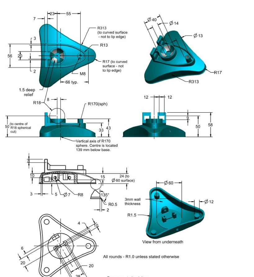
- I am wondering if anyone can advise how to create a shape similar to this. It seems to be an extrusion up to another shape but I am not sure how
2. Also I accidently seemed to mess something up in the model tab as I now can not delete them from there.
Solved! Go to Solution.
ACCEPTED SOLUTION
Accepted Solutions
Oct 01, 2013
08:31 PM
- Mark as New
- Bookmark
- Subscribe
- Mute
- Subscribe to RSS Feed
- Permalink
- Notify Moderator
Please log in to access translation
Oct 01, 2013
08:31 PM
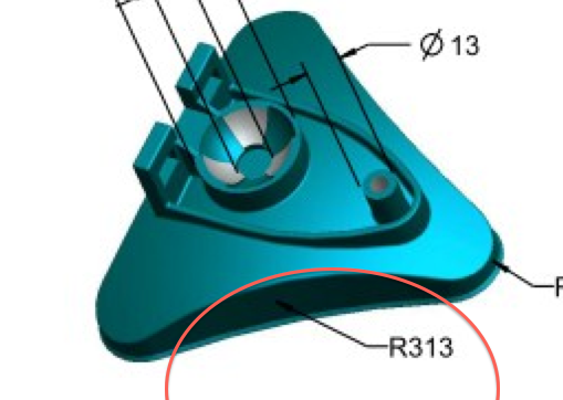
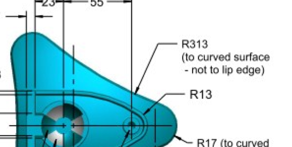
I have to reitterate this comment. I mis-understood the R313 and R17 callouts. This is a fairly straight forward extrude but it is missing the draft requirement.
I created a R170 hemisphere and extruded the triangular shape with the remove "remove material" and flipped the removed material to the outside.
I don't know what the triangular shape is from the limited details provided.
50 REPLIES 50
Oct 01, 2013
03:42 PM
- Mark as New
- Bookmark
- Subscribe
- Mute
- Subscribe to RSS Feed
- Permalink
- Notify Moderator
Please log in to access translation
Oct 01, 2013
03:42 PM
The part was created with a spherical feature as a primary feature and the rest was added and removed.
Oct 01, 2013
08:02 PM
- Mark as New
- Bookmark
- Subscribe
- Mute
- Subscribe to RSS Feed
- Permalink
- Notify Moderator
Please log in to access translation
Oct 01, 2013
08:02 PM
Thanks for replying.
Sorry but I dont exactly understand what you mean.
I started by making a triangle shape then added the rounds at each vertex. I thought from the R313 that I would need to place a large circle so that I could create a remove material extrusion. However it isnt that straightforward as this the height of the vetices are lower than the middle. My thought was I would have to make a r313 extrusion upwards from the bottom to the shape of another circle/arc.
Thanks for your help.
Oct 01, 2013
04:22 PM
- Mark as New
- Bookmark
- Subscribe
- Mute
- Subscribe to RSS Feed
- Permalink
- Notify Moderator
Please log in to access translation
Oct 01, 2013
04:22 PM
Or another way, draw the triangle shape first, and then revolve cut the sphere shape into the top.
OR draw the triangle shape first and then revolve a surface for the sphere and replace the top surface with the sphere surface. but that's kind of a few extra steps.
Oct 01, 2013
08:31 PM
- Mark as New
- Bookmark
- Subscribe
- Mute
- Subscribe to RSS Feed
- Permalink
- Notify Moderator
Please log in to access translation
Oct 01, 2013
08:31 PM
I have to reitterate this comment. I mis-understood the R313 and R17 callouts. This is a fairly straight forward extrude but it is missing the draft requirement.
I created a R170 hemisphere and extruded the triangular shape with the remove "remove material" and flipped the removed material to the outside.
I don't know what the triangular shape is from the limited details provided.
Oct 01, 2013
10:09 PM
- Mark as New
- Bookmark
- Subscribe
- Mute
- Subscribe to RSS Feed
- Permalink
- Notify Moderator
Please log in to access translation
Oct 01, 2013
10:09 PM
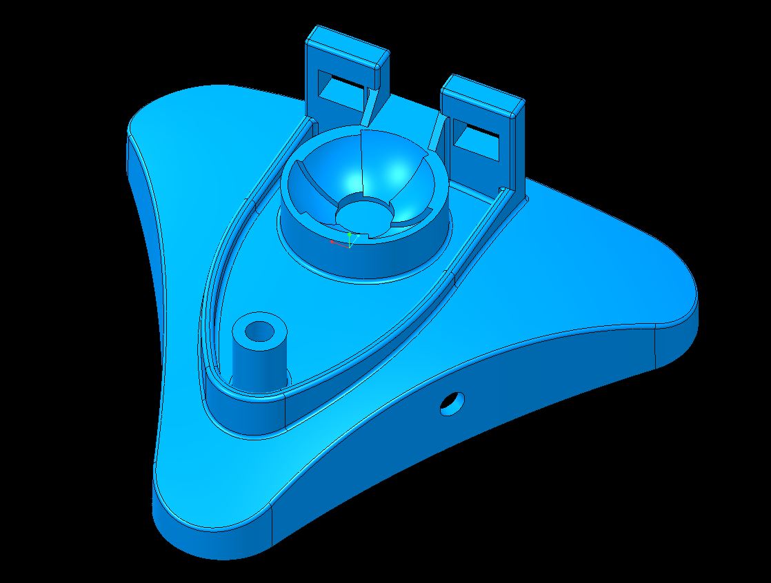
Wow that looks about right. Thanks for all your help so far Antonius!
So you created the hemisphere, drew a triangle shape-extruded and removed the unnecessary material?
also how do I do the hemisphere? I am pretty new to Creo and running it on mac so its a lot of messing about.
Cheers
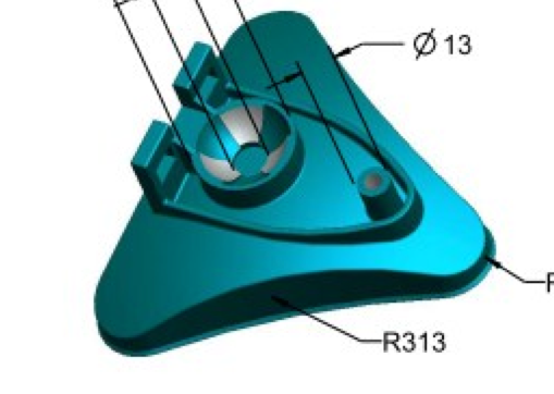
P.S. I've attached a more detailed image incase that helps at all.
Oct 01, 2013
10:14 PM
- Mark as New
- Bookmark
- Subscribe
- Mute
- Subscribe to RSS Feed
- Permalink
- Notify Moderator
Please log in to access translation
Oct 01, 2013
10:14 PM
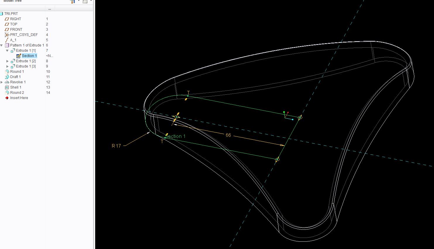
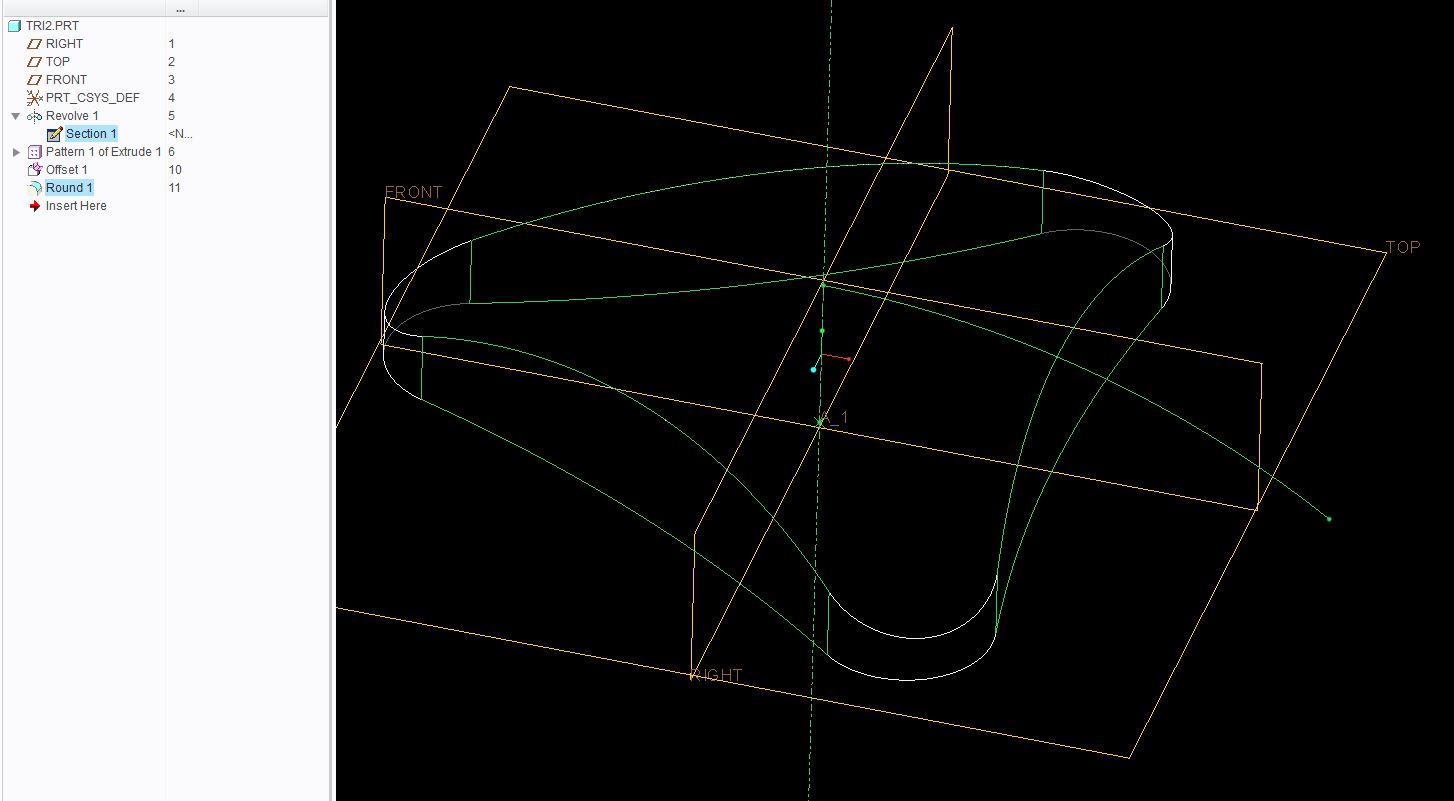
The 1st feature is a solid revolve of a R170 hemisphere (180 degree rotation)
The second feature is the "triangle" shape and is in fact a cut that removed everything -outside- the closed section.
The third feature is a simply round along that top edge.
A subsequent cut can trim the base's height.
Oct 01, 2013
10:16 PM
- Mark as New
- Bookmark
- Subscribe
- Mute
- Subscribe to RSS Feed
- Permalink
- Notify Moderator
Please log in to access translation
Oct 01, 2013
10:16 PM
Oh, that image makes it a lot easier 

Oct 01, 2013
11:26 PM
- Mark as New
- Bookmark
- Subscribe
- Mute
- Subscribe to RSS Feed
- Permalink
- Notify Moderator
Please log in to access translation
Oct 01, 2013
11:26 PM
Different ways....
Oct 01, 2013
11:26 PM
- Mark as New
- Bookmark
- Subscribe
- Mute
- Subscribe to RSS Feed
- Permalink
- Notify Moderator
Please log in to access translation
Oct 01, 2013
11:26 PM
Ah okay, yeah I remember the revolve now.
I've tried with the triangle. Did you sketch it on the curved edge or the bottom and go up?
Ahhh I think I got it if you did go from top. You extruded from top until 139mm above the hemisphere centre?
And re the triangle dimensions I was thinking an equilateral with about 165-170mm from looking at the other dimensions and a bit of research into the component.
I am still tinkering with it as it still looks a bit off.
You've been amazing help!
Oct 01, 2013
11:40 PM
- Mark as New
- Bookmark
- Subscribe
- Mute
- Subscribe to RSS Feed
- Permalink
- Notify Moderator
Please log in to access translation
Oct 01, 2013
11:40 PM
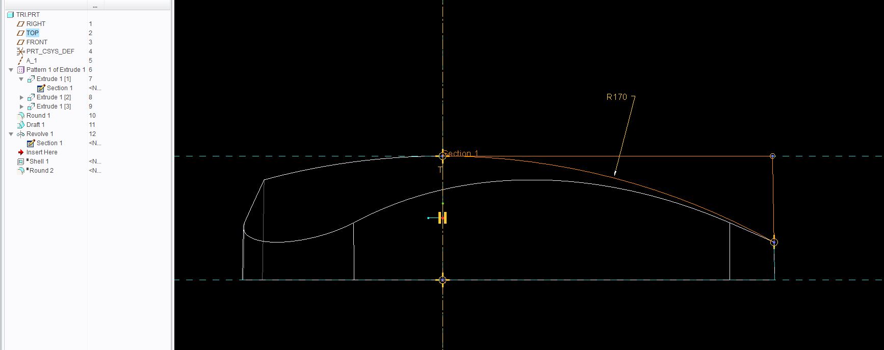
The extrude is from a plane up 31mm (170-139).
I am setting creo up on new computer, Antonius do you know which config file holds the UI stuff? Like which icons are in the quick bar and stuff? It used ot be config.win back in the day now I'm not sure what it is...
Oct 02, 2013
12:46 AM
- Mark as New
- Bookmark
- Subscribe
- Mute
- Subscribe to RSS Feed
- Permalink
- Notify Moderator
Please log in to access translation
Oct 02, 2013
12:46 AM
Matt, from the help files: But I can't find it.
About Saving User Interface Custom Settings
Creo Parametric automatically saves all user interface custom settings to the creo_parametric_customization.ui file that is located in the <user profile>\Application Data\PTC\ProENGINEER\Wildfire\.wf\.Settings\. The customizations of the ribbon, Quick Access toolbar, and Graphics toolbar that you make without opening the Creo Parametric Options dialog box are also automatically saved.If the value of the load_ui_customization_run_dir configuration option is set to yes, then Creo Parametric saves the creo_parametric_customization.ui file to the run directory.
You can save creo_parametric_customization.ui as creo_parametric_admin_customization.ui and place it at creo loadpoint/text to store the CAD administrator settings. The creo_parametric_customization.ui file overrides the creo_parametric_admin_customization.ui file.
Oct 02, 2013
12:57 AM
- Mark as New
- Bookmark
- Subscribe
- Mute
- Subscribe to RSS Feed
- Permalink
- Notify Moderator
Please log in to access translation
Oct 02, 2013
12:57 AM
AH, ok thank you. I will figure that out in the morning.
Oct 02, 2013
01:02 AM
- Mark as New
- Bookmark
- Subscribe
- Mute
- Subscribe to RSS Feed
- Permalink
- Notify Moderator
Please log in to access translation
Oct 02, 2013
01:02 AM
I sent you the path in your private message box.
Oct 01, 2013
11:46 PM
- Mark as New
- Bookmark
- Subscribe
- Mute
- Subscribe to RSS Feed
- Permalink
- Notify Moderator
Please log in to access translation
Oct 01, 2013
11:46 PM
GOT IT!!! Thank you very much Matt and Antonius! Would have been way off without your brilliant help!
See you guys around and thanks again.
Cheers
Oct 02, 2013
12:49 AM
- Mark as New
- Bookmark
- Subscribe
- Mute
- Subscribe to RSS Feed
- Permalink
- Notify Moderator
Please log in to access translation
Oct 02, 2013
12:49 AM
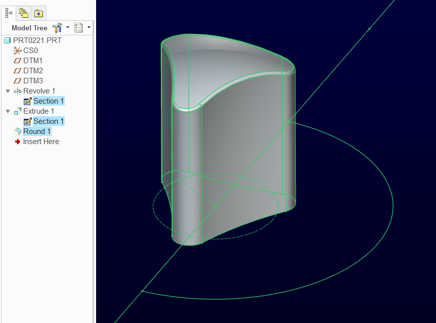
I did this way for the heck of it, too. But not my first choice.
revolve a surface of the arc around (170 rad. by 31mm plane to tangency).
Then extrude up a section form the first way I did, but only 5mm, pattern that around axis 3x 120 degrees.
Then select the top surface of the extrude the click Offset, change it to Replace and pick the original revolved surface.
Then add the 313 rads.
Again, not MY first choice but some people probably like this method.
Oct 02, 2013
12:56 AM
- Mark as New
- Bookmark
- Subscribe
- Mute
- Subscribe to RSS Feed
- Permalink
- Notify Moderator
Please log in to access translation
Oct 02, 2013
12:56 AM
That works too. A lot of ways to skin this cat. But it is only the beginning for the challenge Ioic is facing.
Looks like a fun challenge.
Matt, you have a P.M.
Oct 02, 2013
11:02 AM
- Mark as New
- Bookmark
- Subscribe
- Mute
- Subscribe to RSS Feed
- Permalink
- Notify Moderator
Please log in to access translation
Oct 02, 2013
11:02 AM
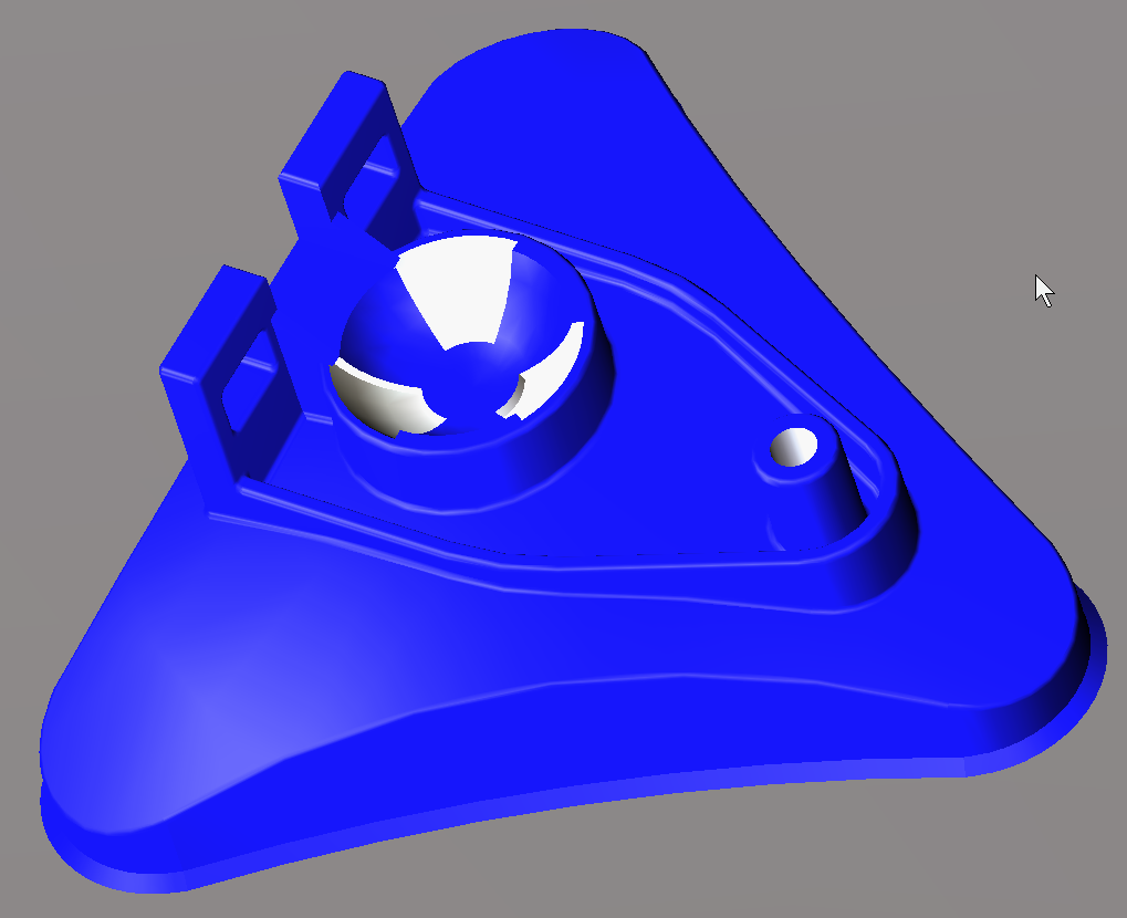
fooling around, not 100%. you can have this model if you want it, but I make no guarantees for the accuracy, some missing numbers on your picture.

Oct 02, 2013
11:18 AM
- Mark as New
- Bookmark
- Subscribe
- Mute
- Subscribe to RSS Feed
- Permalink
- Notify Moderator
Please log in to access translation
Oct 02, 2013
01:25 PM
- Mark as New
- Bookmark
- Subscribe
- Mute
- Subscribe to RSS Feed
- Permalink
- Notify Moderator
Please log in to access translation
Oct 02, 2013
01:25 PM
We really need a life, huh  Nice work guys!
Oct 02, 2013
01:34 PM
- Mark as New
- Bookmark
- Subscribe
- Mute
- Subscribe to RSS Feed
- Permalink
- Notify Moderator
Please log in to access translation
Oct 02, 2013
01:34 PM
You guys are amazing to do it so fast! It is a good challenge but unfortunately that is just the base of the entire assembly hahaha. Though I think this is the hardest part so hopefully after this it should be fine. I'll make sure to get in contact with you guys if I am stuck though!
We are supposed to use our own judgment so as long as it looks right and I use the dimension I can, like you guys have done, I should be able to get it there.
John, what did you do for the reference and sketching for the triangle to get it so it is facing the right way in standard orientation? I am still messing up with my referencing which isn't a big deal with doing the assembly but may be a problem for doing the detail drawings etc.
Also for the lip I am guessing that you just extruded then chamfer from the base of the triangle?
Oct 02, 2013
01:51 PM
- Mark as New
- Bookmark
- Subscribe
- Mute
- Subscribe to RSS Feed
- Permalink
- Notify Moderator
Please log in to access translation
Oct 02, 2013
01:51 PM
You don't have to worry about orientation too much. You can define your views on the fly in the model and somewhat in the drawing. There is a dynamic orientation in the orientation dialog. It can be manipulated in relation to the screen axis or the model axis. Remember to save your views.
On the bottom lip, I might consider a sweep feature.
The drawing you provided is actually quite detailed. I only see a few things missing such as the detail at the bottom of the slot feature on the inside.
But I'll challenge both modelers to now add 2 degrees of draft to the part
Oct 02, 2013
02:04 PM
- Mark as New
- Bookmark
- Subscribe
- Mute
- Subscribe to RSS Feed
- Permalink
- Notify Moderator
Please log in to access translation
Oct 02, 2013
02:04 PM
yeah sweep the bottom lip. Mine already has 1 degree of draft on the trangle shape so  hehe. I've modeled so many parts from prints, I actually really enjoy it.
Oct 02, 2013
05:45 PM
- Mark as New
- Bookmark
- Subscribe
- Mute
- Subscribe to RSS Feed
- Permalink
- Notify Moderator
Please log in to access translation
Oct 02, 2013
05:45 PM
alright got the sweep
What do you suggest about the bottom face material removal?
hahah well you'd love this project Matt-after this there is another 10+ parts. Slowly getting the hang of it. Makes it harder doing it on a mac.
Oct 02, 2013
05:56 PM
- Mark as New
- Bookmark
- Subscribe
- Mute
- Subscribe to RSS Feed
- Permalink
- Notify Moderator
Please log in to access translation
Oct 02, 2013
05:56 PM
Shell feature... but you want to do this early on or it will fail on the 3mm wall.
Oct 03, 2013
04:04 AM
- Mark as New
- Bookmark
- Subscribe
- Mute
- Subscribe to RSS Feed
- Permalink
- Notify Moderator
Please log in to access translation
Oct 03, 2013
04:04 AM
Loic,
The sketch setup for the triangle was as shown:
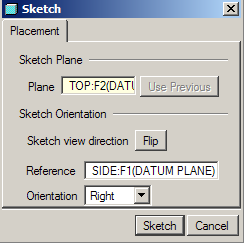
The bottom lip is a Variable Section Sweep using the outline of the base as the trajectory.
The bottom surface was removed using a shell feature straight after applying the spherical cut to the top surface.
As Antonius says, there are tons of ways to model this. All have their own benefits and disadvantages.
I found the trickiest bit was the webs either side of the 'ramp' cut between the tabs. That took a bit of thought, and it's still not properly right.
Have fun trying all the different ways and see which you like best, and don't be afraid to tear it all apart and start again if you decide a different approach would have been more appropriate.
2 degrees of draft...
Well, that's another question!
Cheers,
John
Oct 03, 2013
04:24 AM
- Mark as New
- Bookmark
- Subscribe
- Mute
- Subscribe to RSS Feed
- Permalink
- Notify Moderator
Please log in to access translation
Oct 03, 2013
04:24 AM
John Wayman wrote:
...
2 degrees of draft...Well, that's another question!
...
It was a trick question, of course  When you add draft to the equation, 3D becomes 12D very quickly.
Oct 04, 2013
04:47 PM
- Mark as New
- Bookmark
- Subscribe
- Mute
- Subscribe to RSS Feed
- Permalink
- Notify Moderator
Please log in to access translation
Oct 04, 2013
04:47 PM
Thanks Jon and everyone else. It's tricky but I am working my way through it. Hopefully I won't have any more problems with the base.
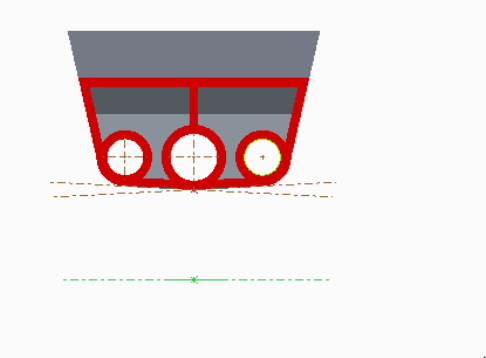
However, I was wondering if I could ask the Creo Think Tank what they thought of this section. I have tried to swept and blend but so far it doesnt work. My idea was to create the kind of winged rectangle on the base and then the square at the bottom and swept blend. But it doesnt seem to be working. Any thoughts?
Oct 04, 2013
05:40 PM
- Mark as New
- Bookmark
- Subscribe
- Mute
- Subscribe to RSS Feed
- Permalink
- Notify Moderator
Please log in to access translation
Oct 04, 2013
05:40 PM
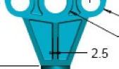
The part above the round shaft? Probably because of the way it is dimensioned, just extrude from center 16 at the bottom and 36 at the top. 22 from center. then turn it and cut away from nothing at the top to the 16 width at the bottom (cut will be 2 triangles, or one triangle and a mirror). I can m
Oct 04, 2013
07:11 PM
- Mark as New
- Bookmark
- Subscribe
- Mute
- Subscribe to RSS Feed
- Permalink
- Notify Moderator
Please log in to access translation
Oct 04, 2013
07:11 PM
Yeah, its the trapezoid kind of form.
- So extrude the square (16) from below (34mm below holes) to the bottom surface?
- Then the angled rectangle on the bottom surface to the side surface of the square extrude?
I think mine is a bit off because the angles dont look quite right.


