
Turn on suggestions
Auto-suggest helps you quickly narrow down your search results by suggesting possible matches as you type.
Showing results for
Please log in to access translation
Turn on suggestions
Auto-suggest helps you quickly narrow down your search results by suggesting possible matches as you type.
Showing results for
Community Tip - You can change your system assigned username to something more personal in your community settings. X
- Community
- Creo+ and Creo Parametric
- 3D Part & Assembly Design
- Re: HELP Modelling base with curvature. Extrude to...
Translate the entire conversation x
Please log in to access translation
Options
- Subscribe to RSS Feed
- Mark Topic as New
- Mark Topic as Read
- Float this Topic for Current User
- Bookmark
- Subscribe
- Mute
- Printer Friendly Page
HELP Modelling base with curvature. Extrude to shape?
Oct 01, 2013
02:42 PM
- Mark as New
- Bookmark
- Subscribe
- Mute
- Subscribe to RSS Feed
- Permalink
- Notify Moderator
Please log in to access translation
Oct 01, 2013
02:42 PM
HELP Modelling base with curvature. Extrude to shape?
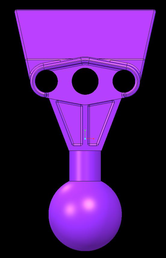
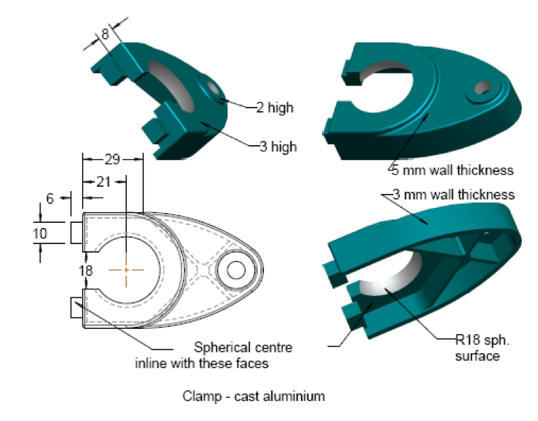
- I am wondering if anyone can advise how to create a shape similar to this. It seems to be an extrusion up to another shape but I am not sure how
2. Also I accidently seemed to mess something up in the model tab as I now can not delete them from there.
Solved! Go to Solution.
50 REPLIES 50
Oct 04, 2013
07:39 PM
- Mark as New
- Bookmark
- Subscribe
- Mute
- Subscribe to RSS Feed
- Permalink
- Notify Moderator
Please log in to access translation
Oct 04, 2013
07:39 PM
Start with the features around the 3 holes. The surface at the bottom of the \/ doesn't actually continue into the "tubes". But I am willing to bet they are parallel to the /\ opposite that region (where the R11 is).
Have alook at the rib feature for that vertical center wall.

Oct 04, 2013
07:40 PM
- Mark as New
- Bookmark
- Subscribe
- Mute
- Subscribe to RSS Feed
- Permalink
- Notify Moderator
Please log in to access translation
Oct 04, 2013
07:40 PM
What version of Creo are you running?
Oct 05, 2013
07:04 PM
- Mark as New
- Bookmark
- Subscribe
- Mute
- Subscribe to RSS Feed
- Permalink
- Notify Moderator
Please log in to access translation
Oct 05, 2013
07:04 PM
I am using creo 2.0
I am not sure I quite get what you mean. I started off by using a reference as my line of centre for my holes (to simplfy the dimensions) So from that line I created the the basic shape of the top part. One thing I am not sure about is where is the bottom placed? I assumed that the rounds more or less continue the two holes on either end but the meeting point seems to be why my shape is slightly off.
That's brilliant Matt. I envy your speed. Maybe you can help with aformentioned question.
Oct 05, 2013
10:20 PM
- Mark as New
- Bookmark
- Subscribe
- Mute
- Subscribe to RSS Feed
- Permalink
- Notify Moderator
Please log in to access translation
Oct 05, 2013
10:20 PM
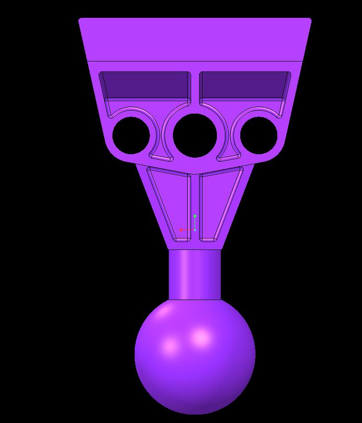
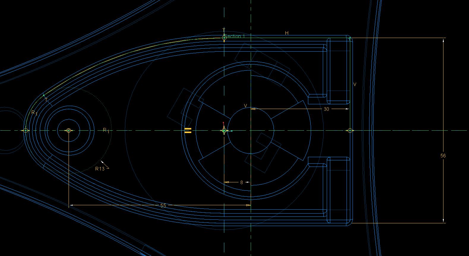
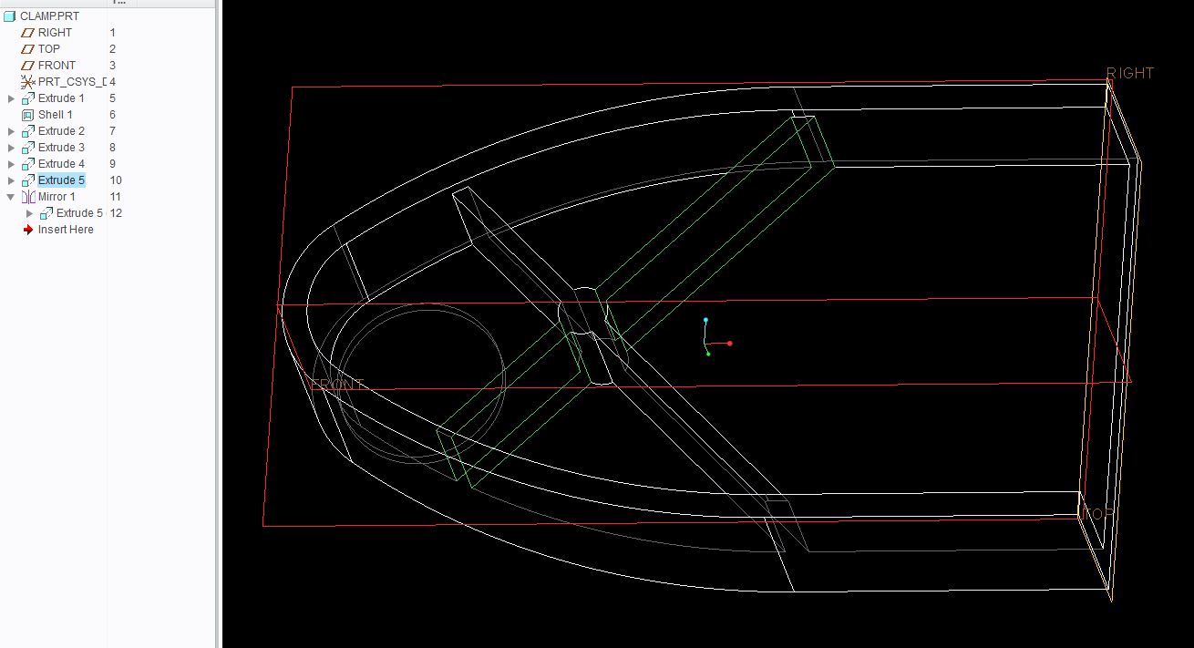
Things got a little off when joining the lower base to the 3-hole feature. Knowing exactly what the numbers applied to was less that intuative. So I began with this:
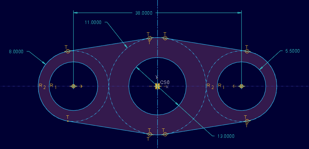
And the numbers stopped making sense when I got tot the merge... something was off. All too often someone will truncate dimensions and they are not as "neet" as they appear. This is what you might be dealing with. This is how I ended up merging stuff:
Oct 05, 2013
10:49 PM
- Mark as New
- Bookmark
- Subscribe
- Mute
- Subscribe to RSS Feed
- Permalink
- Notify Moderator
Please log in to access translation
Oct 05, 2013
10:49 PM
If I understand what you are asking correctly, the bottom center area appears to be "double thick" (5mm). 2.5 from the outside wall and 2.5 from the center hole. Your above picture looks like you modeled it at 2.5, so your shape looks more flat on the bottom.
Oct 05, 2013
11:22 PM
- Mark as New
- Bookmark
- Subscribe
- Mute
- Subscribe to RSS Feed
- Permalink
- Notify Moderator
Please log in to access translation
Oct 05, 2013
11:22 PM
Aha... yes... the R11, R8 and 38 are the key references to determine the angles.
And the center hole diamter is missing! I don't like missing dimensions 
Oct 07, 2013
05:51 PM
- Mark as New
- Bookmark
- Subscribe
- Mute
- Subscribe to RSS Feed
- Permalink
- Notify Moderator
Please log in to access translation
Oct 07, 2013
05:51 PM
Hi guys,
So I think Ive fixed up the lower angle joint. Easier when you work with the other side.
However I am still unsure as to what you suggest for the trapezoid figure below this section. I have tried to create a square based prism to the bottom and then extend two shapes to this but it hasnt worked so far.
With this I should be more or less wrapped for this part and hopefully move on.
hahah Matt well I will make sure to post if I have trouble with the next one.
Again thanks for your help guys.
Loic
Oct 07, 2013
05:59 PM
- Mark as New
- Bookmark
- Subscribe
- Mute
- Subscribe to RSS Feed
- Permalink
- Notify Moderator
Please log in to access translation
Oct 07, 2013
05:59 PM
Can you post some pics of what area you are talking about?
Oct 07, 2013
06:03 PM
- Mark as New
- Bookmark
- Subscribe
- Mute
- Subscribe to RSS Feed
- Permalink
- Notify Moderator
Please log in to access translation
Oct 07, 2013
06:03 PM
Hi Matt
I am refering to the part above the round part we discussed earlier. I just wanted to clarify what you meant by:
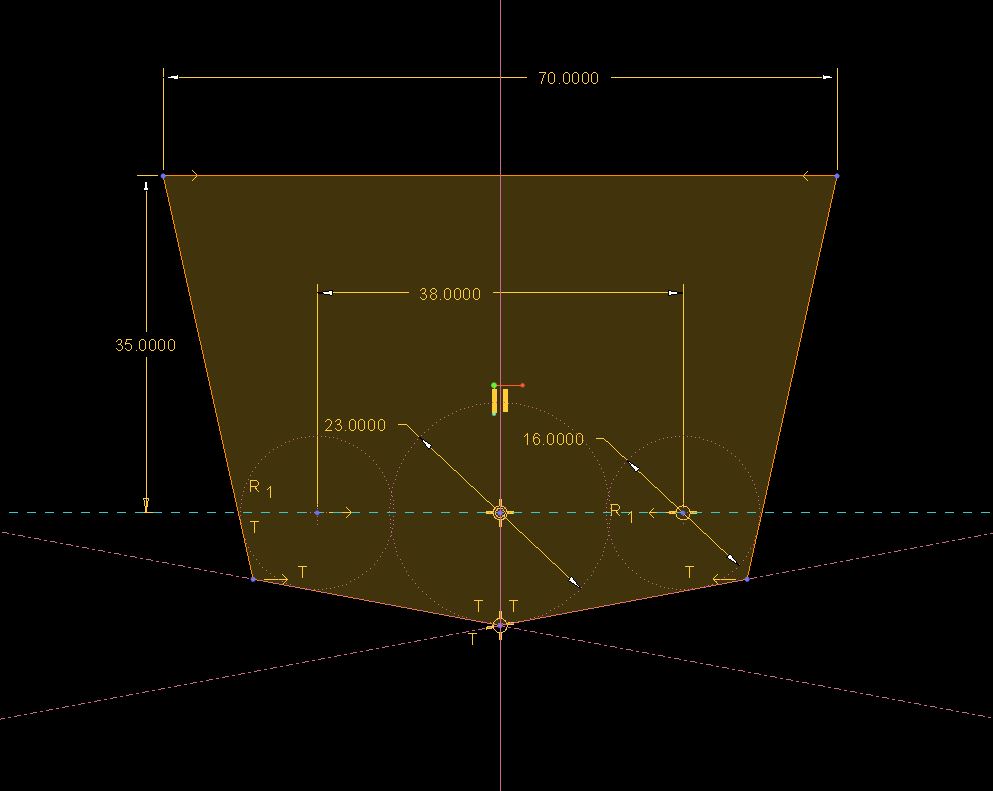
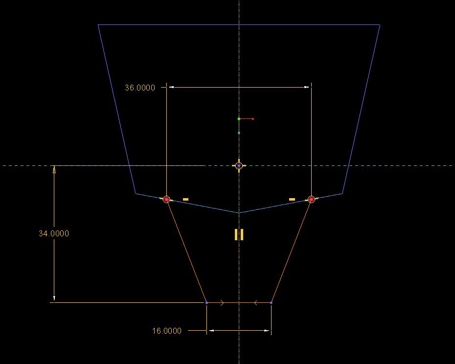
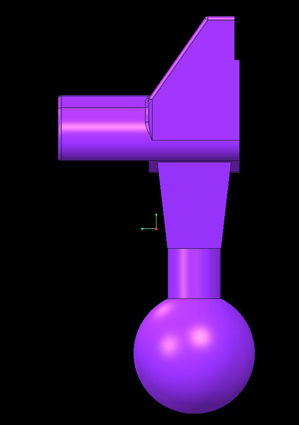
" part above the round shaft? Probably because of the way it is dimensioned, just extrude from center 16 at the bottom and 36 at the top. 22 from center. then turn it and cut away from nothing at the top to the 16 width at the bottom (cut will be 2 triangles, or one triangle and a mirror). I can m"
Cheers,
Loic
Oct 07, 2013
11:08 PM
- Mark as New
- Bookmark
- Subscribe
- Mute
- Subscribe to RSS Feed
- Permalink
- Notify Moderator
Please log in to access translation
Oct 07, 2013
11:08 PM
I made a simple sketch. Does this help at all?
Oct 07, 2013
06:06 PM
- Mark as New
- Bookmark
- Subscribe
- Mute
- Subscribe to RSS Feed
- Permalink
- Notify Moderator
Please log in to access translation
Oct 07, 2013
06:06 PM
The trapezoid can be extruded to the full 27 and then trimmed to the angle with a cut normal to the extrusion.
Several ways to make it. I made it using just the 2.5 wall and added a wall to fill the center.
Oct 04, 2013
10:34 PM
- Mark as New
- Bookmark
- Subscribe
- Mute
- Subscribe to RSS Feed
- Permalink
- Notify Moderator
Please log in to access translation
Oct 04, 2013
10:34 PM
I'm not 100% happy with the way I modeled it. Not really the best methods used. Couple features in there don't really need.
Oct 05, 2013
11:05 PM
- Mark as New
- Bookmark
- Subscribe
- Mute
- Subscribe to RSS Feed
- Permalink
- Notify Moderator
Please log in to access translation
Oct 05, 2013
11:05 PM
Matt, you got there pretty much the same way I did. The only difference in interpretation is the upper core removal where I stayed with a 2.5mm wall on the angled face.
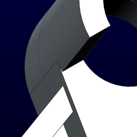
Also have a look at extrude 9... I just used the optional second extrude direction to fill the small void in extrude 6.
I also see where you had trouble with the fillets in the bottom core removal where the center rib meets the R11. Since rounds don't like jumping boundaries, I had to extrude it.
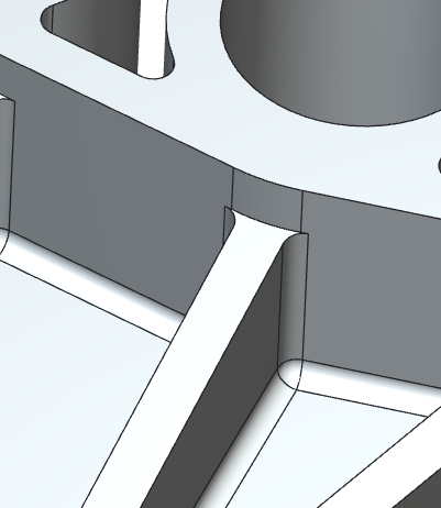
Of course, leaving the R11 sharp and radiusing it later would also have solved it. But it is one of those things that can cost you a lot of clicking to find out just what failed.
Oct 05, 2013
11:45 PM
- Mark as New
- Bookmark
- Subscribe
- Mute
- Subscribe to RSS Feed
- Permalink
- Notify Moderator
Please log in to access translation
Oct 05, 2013
11:45 PM
Yeah there were a couple things I missed at first and then didn't try to make the tree nicer after. I started out only planning to model the bottom of the part and then decided, screw it I'll just keep going and see how it looks.
So you're right I could have re-ordered 9, extrude 5 I didn't even need. At first I didn't realize how deep the angle went (cutting into that area).
Are you saying because mine is R11.5 at the bottom? I just carried the wall thickness down to the bottom, I didn't even try it at R11.
Loic, come on, we're tired of this one, next part, next part.... 
Oct 05, 2013
11:56 PM
- Mark as New
- Bookmark
- Subscribe
- Mute
- Subscribe to RSS Feed
- Permalink
- Notify Moderator
Please log in to access translation
Oct 05, 2013
11:56 PM
I'm going through yours now. Yep, I am assuming the center major diameter is 22 where you have 23. You didn't run into the round limitation because it didn't try to cross over the tangent seam. Easy to do if you assume a 2.5mm wall with the diameter 18 center OD.
I have uploaded the step of what I came up with...
Oct 05, 2013
11:58 PM
- Mark as New
- Bookmark
- Subscribe
- Mute
- Subscribe to RSS Feed
- Permalink
- Notify Moderator
Please log in to access translation
Oct 05, 2013
11:58 PM
Actually what I find interesting is that in making the changes, most of the rounds fail... but a simple edit definition fixes them without any real changes. Shouldn't regen fix these on their own?
Oct 19, 2013
07:47 AM
- Mark as New
- Bookmark
- Subscribe
- Mute
- Subscribe to RSS Feed
- Permalink
- Notify Moderator
Please log in to access translation
Oct 19, 2013
07:47 AM
HI Guys,
so heres the last pozt to wrap it up
- Clamp feature how to especially
- "x" form
- remove material
- base dimensions
- Is it possible to do a shell with a dual shell? (top 3mm and bottom 5mm)
- For the previous part, remember the trapezoid section above the cylinder and ball. So far i completd the design but it isnt allowing me to shell out this drawing-Maybe some advice?
- Excuse me for dredging up the base again but can anyone explain the barrier type feature? On the top face.
CHeer fellas and see you.
Oct 19, 2013
01:41 PM
- Mark as New
- Bookmark
- Subscribe
- Mute
- Subscribe to RSS Feed
- Permalink
- Notify Moderator
Please log in to access translation
Oct 19, 2013
01:41 PM
If those are the only numbers you have, a couple ideas are to create this new part in assembly mode with the other part. Or start measuring the other part and writing the numbers down or make yourself a print.
I have to look at the rest in a bit.
Oct 19, 2013
02:55 PM
- Mark as New
- Bookmark
- Subscribe
- Mute
- Subscribe to RSS Feed
- Permalink
- Notify Moderator
Please log in to access translation
Oct 19, 2013
02:55 PM
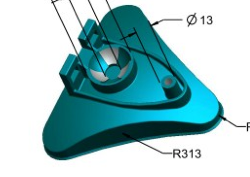
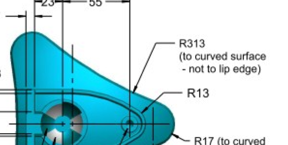
This is what that shape looks like to me from that other part.
Oct 19, 2013
03:44 PM
- Mark as New
- Bookmark
- Subscribe
- Mute
- Subscribe to RSS Feed
- Permalink
- Notify Moderator
Please log in to access translation
Oct 19, 2013
03:44 PM
Oct 20, 2013
02:31 PM
- Mark as New
- Bookmark
- Subscribe
- Mute
- Subscribe to RSS Feed
- Permalink
- Notify Moderator
Please log in to access translation
Oct 20, 2013
02:31 PM
loic bishop wrote:
HI Guys,
so heres the last pozt to wrap it up
- Clamp feature how to especially
- "x" form The X-Form is a rib function. Can be done with extrude, but ribs are a nice feature to explore.
- remove material Remove material is simply the opposite of adding material in the extrude and revolve features. There is a specific button in the dialog for this.
- base dimensions Yep, as Matt said, these dimensions were included in the earier excersize.
- Is it possible to do a shell with a dual shell? (top 3mm and bottom 5mm) I don't know that I would even shell this part. Shells fail if
rounds have been applied. In this case, since it is simple enough, I would extrude either the top or the side walls, and extrude the other from the previous geometry.- For the previous part, remember the trapezoid section above the cylinder and ball. So far i completd the design but it isnt allowing me to shell out this drawing-Maybe some advice? Again, shell is touchy. It -must- shell all features. If rounds are specified that go to zero, it will fail. In many cases, I prefer creating surfaces and then adding thickness instead to solidify things. If it gets really complex, you might create the inside and outside quilts and solidify once stiched and closed. None of your parts have yet justified -extreme- measures.
- Excuse me for dredging up the base again but can anyone explain the barrier type feature? On the top face. I see that as an extrude. Specifically where are you having difficulties?
CHeer fellas and see you.

- « Previous
-
- 1
- 2
- Next »


