
Turn on suggestions
Auto-suggest helps you quickly narrow down your search results by suggesting possible matches as you type.
Showing results for
Please log in to access translation
Turn on suggestions
Auto-suggest helps you quickly narrow down your search results by suggesting possible matches as you type.
Showing results for
Community Tip - Have a PTC product question you need answered fast? Chances are someone has asked it before. Learn about the community search. X
- Community
- Creo+ and Creo Parametric
- 3D Part & Assembly Design
- Re: Harness drawing best practices (Help!)
Translate the entire conversation x
Please log in to access translation
Options
- Subscribe to RSS Feed
- Mark Topic as New
- Mark Topic as Read
- Float this Topic for Current User
- Bookmark
- Subscribe
- Mute
- Printer Friendly Page
Harness drawing best practices (Help!)
Dec 10, 2021
10:03 AM
- Mark as New
- Bookmark
- Subscribe
- Mute
- Subscribe to RSS Feed
- Permalink
- Notify Moderator
Please log in to access translation
Dec 10, 2021
10:03 AM
Harness drawing best practices (Help!)
I am very new to cabling and I'm in the process of creating my first flat harness drawing. Flattening the harness took a little time to figure out, but now that I'm creating the drawing I realize the flatten state is a bit of a mess and I'm probably not doing things the correct way. I have been unable to find tutorials or documentation to point me in the right direction, so I figured I would ask here.
Below is a screen shot from my drawing showing what is possibly the worst location of my harness. I have two connectors that plug into a controller and two bundles that go in different directions (one large bundle, one small bundle). I realize that this is nearly impossible to put any dimensions on:

What I would like to get to is something more like the image below where the two connectors split off and simple length dimension can be added. I know that I can change the cable from thick to centerline view, but I still have a mess of individual wires (which are driving my pin tables) and I don't see a simple way to make a simple centerline from the bundle to the connector.

What is the best way to clean this up so that a) my individual wires are still routed correctly and driving my pin tables and b) my harness will flatten with a simple/single centerline from the main branch to the connector?
Labels:
- Labels:
-
2D Drawing
-
Routed Syst. Design
11 REPLIES 11
Dec 13, 2021
07:47 AM
- Mark as New
- Bookmark
- Subscribe
- Mute
- Subscribe to RSS Feed
- Permalink
- Notify Moderator
Please log in to access translation
Dec 13, 2021
07:47 AM
Hello TractorGuy,
Thank you for posting this request.
In order to help you, PTC proposes trainings and tutorials around cabling.
For trainings requests you can access to: https://www.ptc.com/en/ptc-university/instructor-led-training/?utm_source=Learning_Connector&utm_medium=remarketing&utm_campaign=Training_General_Learning_Connector_CLC&utm_content=Training_General_Learning_Connector_CLC-remarketing-Ad_banners_for_Learning_Connector_site-43676&cl1=Training_General_L...
For tutorials please visit: https://learningconnector.ptc.com/search/tutorials?product=Creo%20Parametric&category=Cabling
Hope this will help you to get better result with HMX.
Regards
Jean Claude
Dec 13, 2021
04:56 PM
- Mark as New
- Bookmark
- Subscribe
- Mute
- Subscribe to RSS Feed
- Permalink
- Notify Moderator
Please log in to access translation
Dec 13, 2021
04:56 PM
"Take training" is not really an answer to my question.
Dec 14, 2021
03:45 AM
- Mark as New
- Bookmark
- Subscribe
- Mute
- Subscribe to RSS Feed
- Permalink
- Notify Moderator
Please log in to access translation
Dec 14, 2021
03:45 AM
Hi TractorGuy
What about the tutorials?
Dec 14, 2021
08:08 AM
- Mark as New
- Bookmark
- Subscribe
- Mute
- Subscribe to RSS Feed
- Permalink
- Notify Moderator
Please log in to access translation
Dec 14, 2021
08:08 AM
I got to the point I am now by using tutorials and training. My problem is that I wasn't able to find the answer to my issue looking through the training materials. It's possible I overlooked something since I rushed through the materials, so I have asked the community to help point me in the right direction.
Dec 15, 2021
03:23 PM
- Mark as New
- Bookmark
- Subscribe
- Mute
- Subscribe to RSS Feed
- Permalink
- Notify Moderator
Please log in to access translation
Dec 15, 2021
03:23 PM
I went through the tutorials again and still did not find the answer to my question. Also, my company is on a custom version of Creo 2.0 so most of the training/tutorials do not apply to my version. The other issue is that most of the training is focused on routing wires and very little is available for making drawings. I will ask the question once again in hopes to clarify what I'm trying to figure out.
The prototype harness that I am trying to create has several wires routed through flexible conduit. I need a certain amount of exposed wire before the connector for a few reasons. I am also trying to make a flat instance of this harness model so that I can create a reference drawing to use for building the prototype. The problem is that the harness does not flatten without the wires being a big mess. I would like to either a) improve the way the wires flatten so that the individual wires fan out neatly or b) show a simplified version of the wire between the connector and wire bundle in the conduit.
Dec 16, 2021
07:59 AM
- Mark as New
- Bookmark
- Subscribe
- Mute
- Subscribe to RSS Feed
- Permalink
- Notify Moderator
Please log in to access translation
Dec 16, 2021
07:59 AM
I am not an expert in routing and we do not make the flat pattern drawings. We often just detail them in their 3D formed shape. That being said we have done things similar to what you are requesting and to solve them we typically make a separate model or assembly that shows it how we want it and add that to the drawing. I am sure this isn't the response you wanted and hopefully someone else will chime in but if not then you have at least one other perspective.
May 18, 2022
10:39 AM
- Mark as New
- Bookmark
- Subscribe
- Mute
- Subscribe to RSS Feed
- Permalink
- Notify Moderator
Please log in to access translation
May 18, 2022
10:39 AM
The link no longer works.
May 18, 2022
11:03 AM
- Mark as New
- Bookmark
- Subscribe
- Mute
- Subscribe to RSS Feed
- Permalink
- Notify Moderator
Please log in to access translation
May 18, 2022
11:03 AM
Both links worked for me.
The Learning Connector link does show an error at the top of the page, but by selecting some of the options you can find tutorials on Creo Schematics and Creo Cabling. Piping is not much different than Cabling, just less flexibility in the way pipes route versus cables.
Mar 08, 2022
08:57 AM
- Mark as New
- Bookmark
- Subscribe
- Mute
- Subscribe to RSS Feed
- Permalink
- Notify Moderator
Please log in to access translation
Mar 08, 2022
08:57 AM
Ok, 3 months later and I'm no closer to making a usable drawing for constructing a wiring harness. I can not understand how anyone keeps their sanity using this software to do anything productive. Here is a short list of the issues I can not resolve:
- I can not keep the connectors in line with the harness. My connectors have even numbers of wires which means I have to flatten to one side or the other and can not keep it centered.
- It is impossible to fan out all of the wires to a connector unless you want to spend an entire day adding bends and twists to the wires so they will reach.
- Connectors do not stay with backshells. I have a 90° 64 pin connector that has a backshell which assembles correctly to the harness. I still have not determined how to get the connector to come in and assemble to the backhshell correctly and it is always angled in the wrong plane.
Seriously, how the hell do people make wiring harness drawings with this garbage?
Mar 09, 2022
12:46 AM
- Mark as New
- Bookmark
- Subscribe
- Mute
- Subscribe to RSS Feed
- Permalink
- Notify Moderator
Please log in to access translation
Mar 09, 2022
12:46 AM
Take a look at Harness manufacturing extension (hmx)
But from Creo 3, I think...
Mar 15, 2022
11:53 AM
- Mark as New
- Bookmark
- Subscribe
- Mute
- Subscribe to RSS Feed
- Permalink
- Notify Moderator
Please log in to access translation
Mar 15, 2022
11:53 AM
Yes, it does take some time to get acquainted with the cabling module. But in the end I (personally) like the Creo cabling module actually more than the other option that we have… the Solidworks cabling (Except for creating the drawings).
We needed to take the basic cabling course before any of us understood anything about the cabling module. Fortunately we have gotten to a point that it is fairly easy to add small and even some larger cable assemblies into our devices.
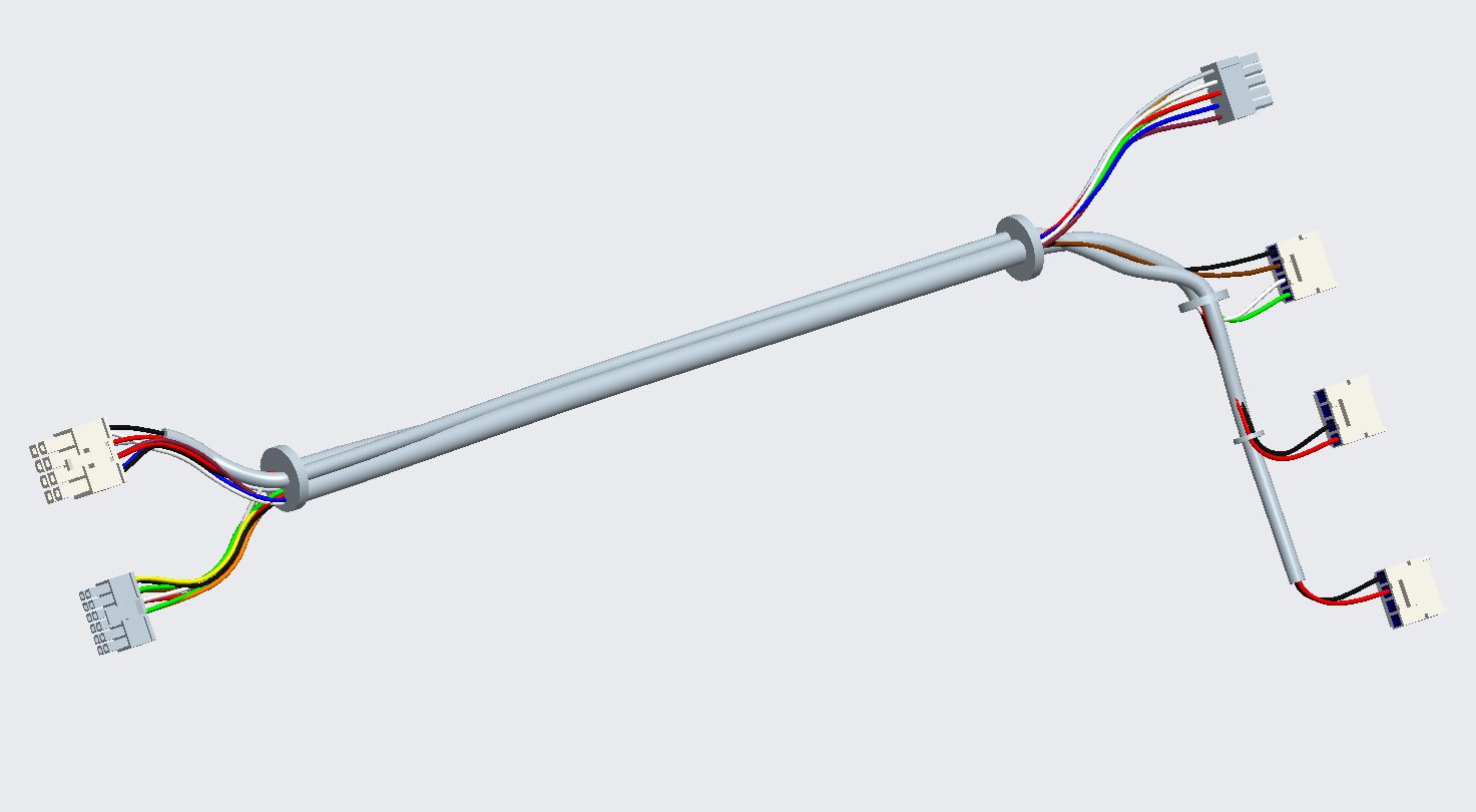
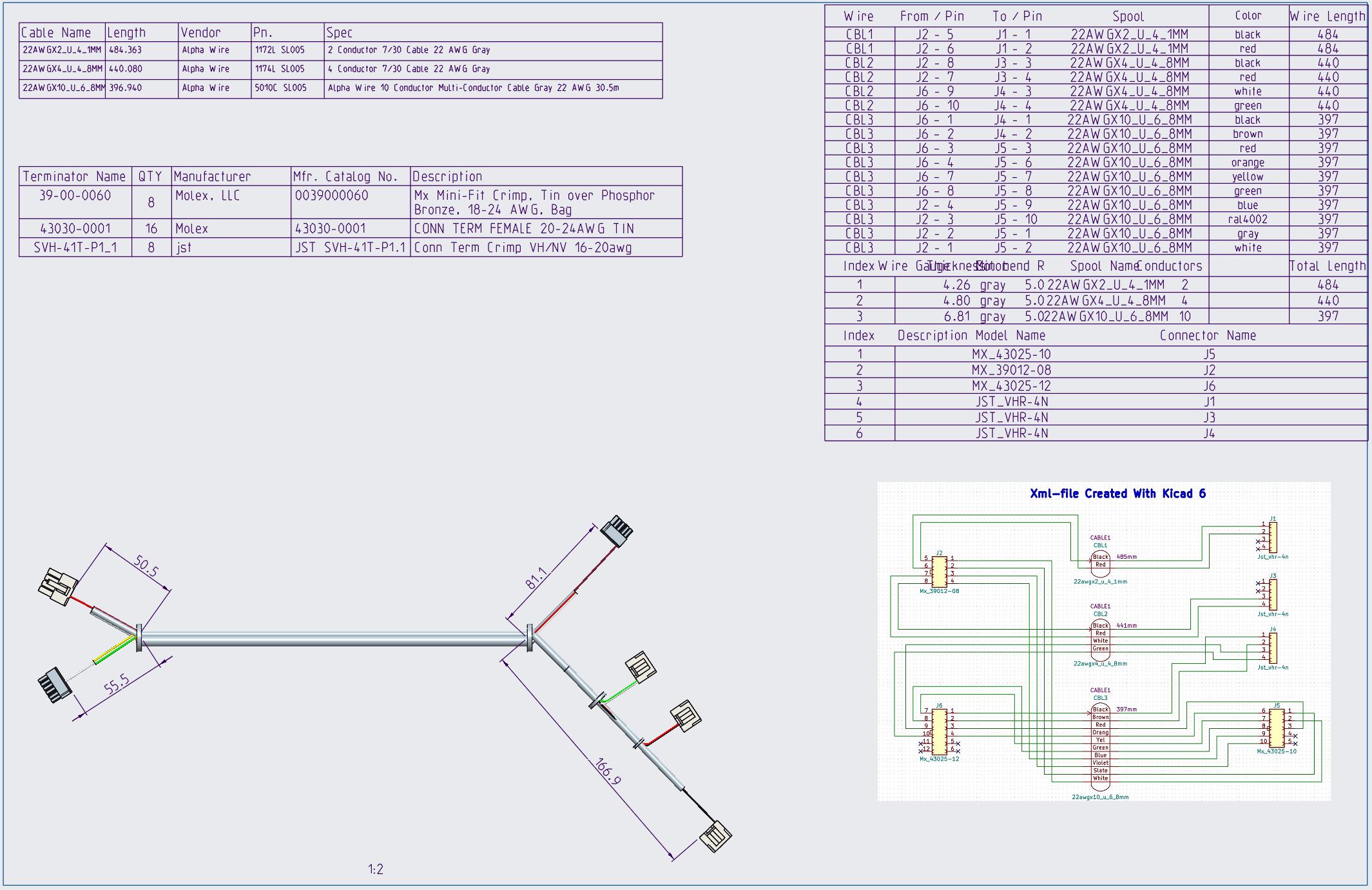
You can get fairly accurate split length dimensions from the flat harness assembly (see image “whole_drw.jpg”). What I understood is that the HMX-extension (Harness Manufacturing Extension) creates these splits (and lengths) automatically. Unfortunately, though, we do not have HMX license so I must always do the File-Manufacturing-Harness –flat diagrams for the cables. Fortunately, after doing so many of those, I have grown used to doing the “regular” flat diagrams. They work pretty well in most cases (not always). There are some good design practices in flattening the cables…
For our cable guys the most important tips are...
1. Make your cable network as good as possible.
- The cable sheaths are cut to some network point close to the connector. Wires also bundle nicely around the cable network (you can select flat or round). Sometimes the cable routing fails if your network has too tight turns.
- it seems that if you add a network point to your network then all your flat harness assemblies break. So make sure that the cable routes are finished before starting to flatten the cables to make the drawings.
2. Automatic flattening usually has all the wires going all over the connectors. Only a single wire is connected physically. Your flat diagram looks neater if you delete all the “loose”-segments (see images “segments_after_autofan.jpg” and “segments_deleted.jpg” (or flatten manually).
3. Of course… always use a skeleton for your wiring assemblies. Use shrinkwrap to copy the necessary surfaces etc. from the main assembly.
- Normally our skeleton contains the coordinates and the connectors are mated to those coordinates.
- Skeleton also includes the axes, surfaces etc. for the network routes.
- This example does not have any skeleton. I added the mate coordinates to the top of the model tree.
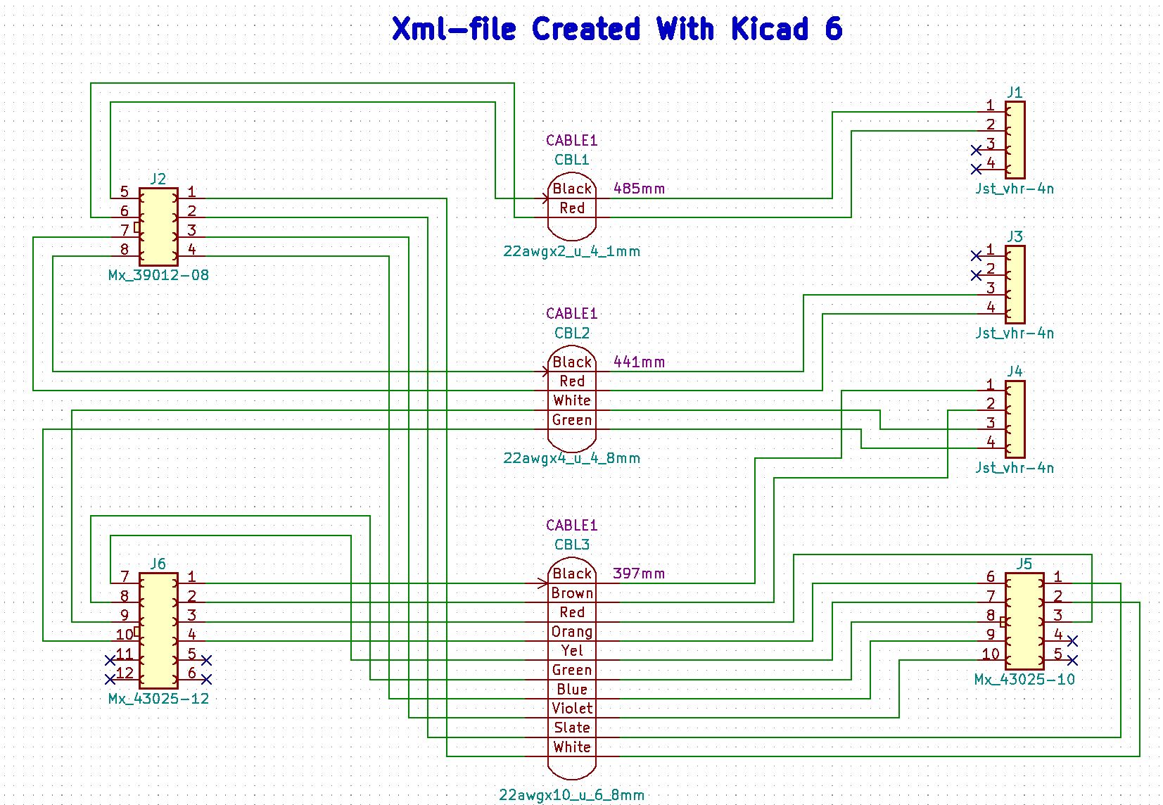
4. Always use schematic to create the xml-file. Only insane people want to manually route cables (meaning that you manually select pin 1 from connector 1… goes to pin x on connector y) you can try it once… yes it works also. We use kicad (free, but Python programming skills required) and Creo Schematic is ok also (except that it is pain to get started with Creo Schematic). Some people use Excel to generate the xml-files… even that is better than manual routing. The example zip package contains the xml-file from Kicad (text file) which was used to create this example.
With a perfect network you can route all your wires and cables with just a few clicks (select “Route Cables → Binoculars → select all routable wires and cables and press “Apply”).
I attach all the design files of the demo here also. Unfortunately they are Creo 4.0 files so you have to have 4.0 or later version. But all Cabling features are still the same in Creo 2.0 (vs 4.0). Our previous version was 2.0 and even the few “features” are still the same in 4.0 (I tried version 7 and the cabling module was more or less identical to Creo 2.0).
Best Regards,
Lars KaputtCbl


