Community Tip - Learn all about PTC Community Badges. Engage with PTC and see how many you can earn! X
- Community
- Creo+ and Creo Parametric
- 3D Part & Assembly Design
- Re: Helix sweep, flat end
- Subscribe to RSS Feed
- Mark Topic as New
- Mark Topic as Read
- Float this Topic for Current User
- Bookmark
- Subscribe
- Mute
- Printer Friendly Page
Helix sweep, flat end
- Mark as New
- Bookmark
- Subscribe
- Mute
- Subscribe to RSS Feed
- Permalink
- Notify Moderator
Helix sweep, flat end
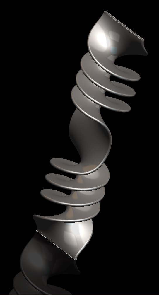
I am trying to create a screw type part. The best way to imagine it is a flat rectangular bar that is twisted. I know how to make a screw, but i always end with edges i dont want and then cannot find a way to clean it up nicely.
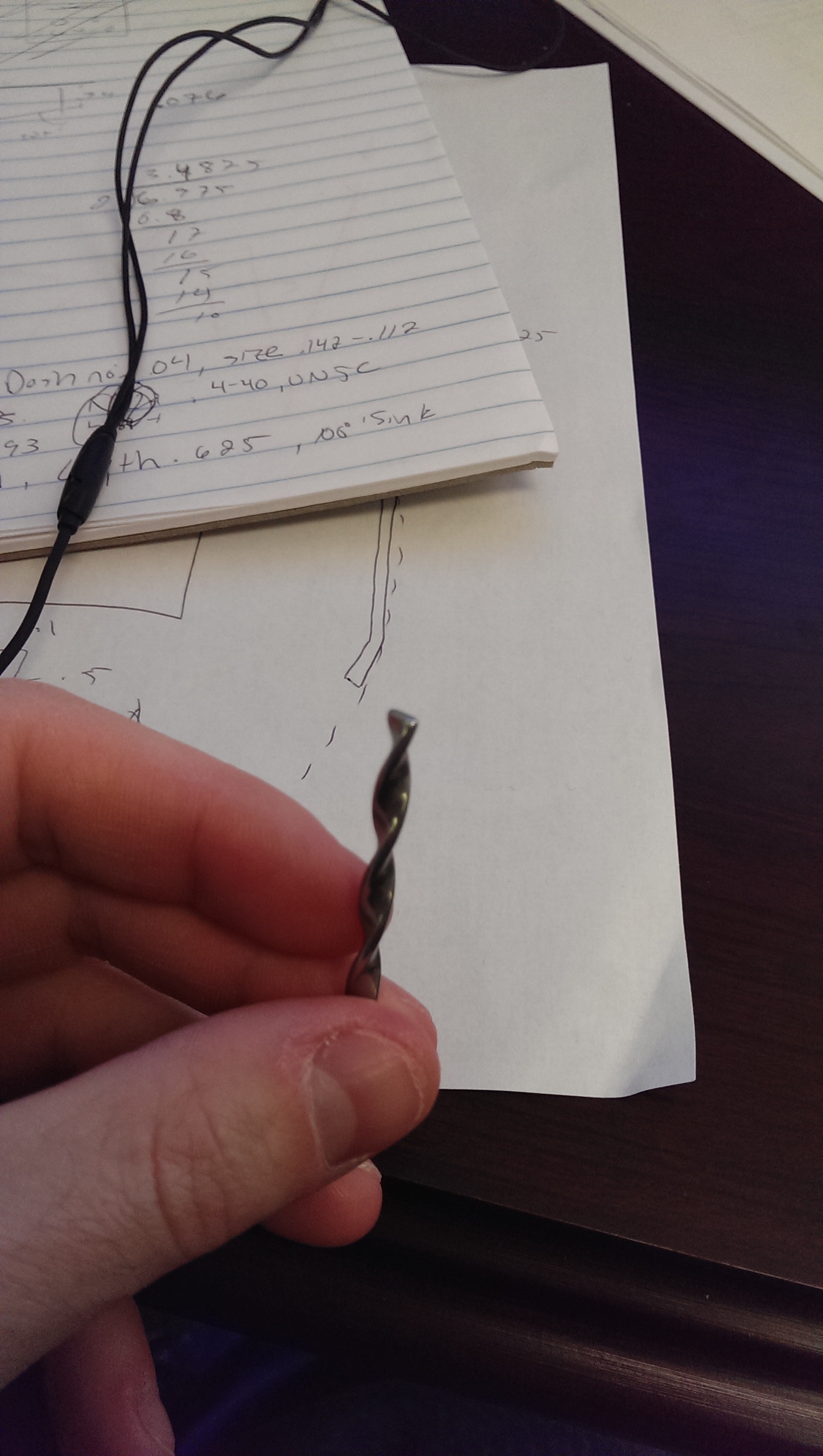
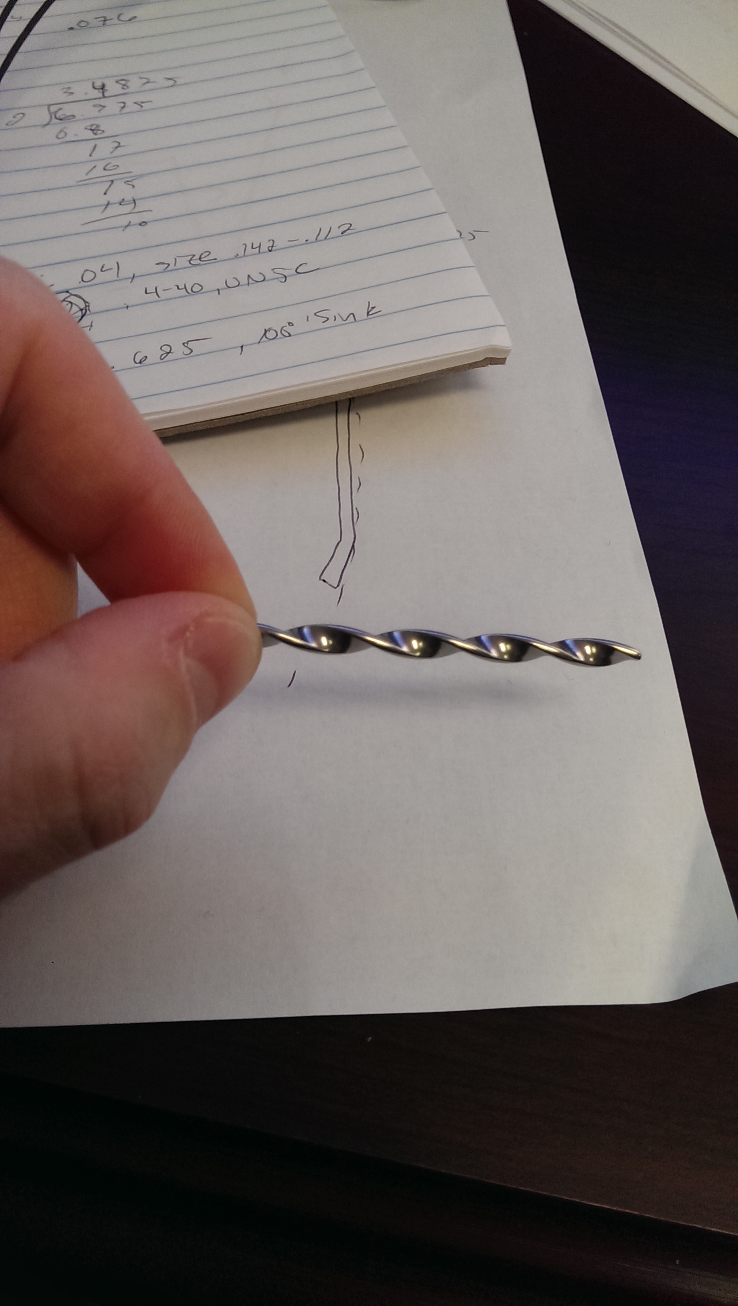
This thread is inactive and closed by the PTC Community Management Team. If you would like to provide a reply and re-open this thread, please notify the moderator and reference the thread. You may also use "Start a topic" button to ask a new question. Please be sure to include what version of the PTC product you are using so another community member knowledgeable about your version may be able to assist.
- Labels:
-
General
- Mark as New
- Bookmark
- Subscribe
- Mute
- Subscribe to RSS Feed
- Permalink
- Notify Moderator
I think there are better solution, but this is without any equation.
- Mark as New
- Bookmark
- Subscribe
- Mute
- Subscribe to RSS Feed
- Permalink
- Notify Moderator
Might want to look at this: How to use get uniform pitch in warp/twist
You may need to model it slightly longer and then just cut the ends off.
- Mark as New
- Bookmark
- Subscribe
- Mute
- Subscribe to RSS Feed
- Permalink
- Notify Moderator
As always, the answer is.....it depends. From what I see, it's a constant helix simply cut off at both ends. Helical sweep, or a VSS (Variable Section Sweep) will easily do that. Simple. IF, however, you need the twist to change and it to end up tangent to the long axis on both lead-in and lead-out, then you need to use either the Warp command (tough to get exactly what you want, but very powerful) or a VSS with the proper trajectory.
Without more accurate info on EXACTLY what you want, it.....depends. ![]()
- Mark as New
- Bookmark
- Subscribe
- Mute
- Subscribe to RSS Feed
- Permalink
- Notify Moderator
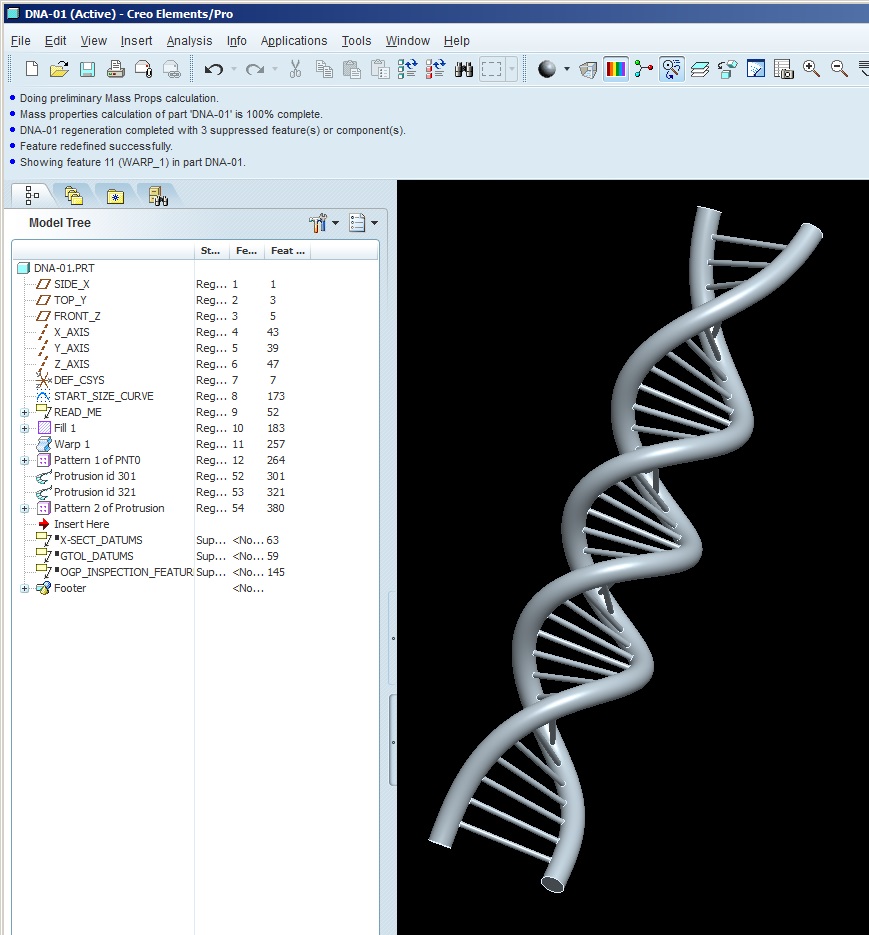
The DNA comment had me thinking. So I was messing around, but if you zoom in everything is pretty distorted, disappointing actually.
- Mark as New
- Bookmark
- Subscribe
- Mute
- Subscribe to RSS Feed
- Permalink
- Notify Moderator
Well, that shouldn't be surprising considering that you're twisting existing geometry. I would expect that. It's taking circular cross-sections of the rails normal to the longitudinal axis, and twisting the geometry around that, leaving the sections round.....normal to that axis. Which "smears" the circular section into an ellipse if viewing it along the helical trajectory, and it smears the rungs as well. The way to probably use a warp like that, would be to use a flat surface, pattern points along an edge, twist that, then use the edges as trajectories for the rails, and then pattern the rungs from the points.
- Mark as New
- Bookmark
- Subscribe
- Mute
- Subscribe to RSS Feed
- Permalink
- Notify Moderator
- Mark as New
- Bookmark
- Subscribe
- Mute
- Subscribe to RSS Feed
- Permalink
- Notify Moderator
Ok, I made a quick model. You can play with "offsetting" the marque on both ends (use absolute, then the offset on both ends is in "units"), to minimize the tangency, but that's not really a cure because you might lose some twists.
Anyways, like I said, without knowing the exact desired geometry...... ![]()
- Mark as New
- Bookmark
- Subscribe
- Mute
- Subscribe to RSS Feed
- Permalink
- Notify Moderator
proe wildfire 4.0 file attached,please have a look.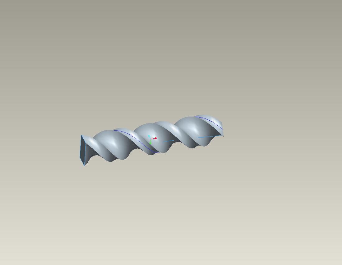
- Mark as New
- Bookmark
- Subscribe
- Mute
- Subscribe to RSS Feed
- Permalink
- Notify Moderator
In the proper conditions, even if you could control the twist in a constant pitch IRL, the "section" of the part would warp into a twist. So any straight cross section in the actual part would not be a true representation of the native material's shape upon close inspection.
That said, duplicate the exact shape and treat the ends for further processing. With the constant pitch, that shouldn't be difficult.
This is the technique that has proven quite reliable;
make a VSS of the center surface; thicken it about the middle; and add a full round on each edge.
Now you will see the true and warped section at the ends when you twist metal in this manner.
- Mark as New
- Bookmark
- Subscribe
- Mute
- Subscribe to RSS Feed
- Permalink
- Notify Moderator
In sheet metal we have twist option. that may be useful for your need.
- Mark as New
- Bookmark
- Subscribe
- Mute
- Subscribe to RSS Feed
- Permalink
- Notify Moderator
IF it does not need subsequent features that will prevent it from being a sheetmetal part. That's my main issue with sheetmetal. There should be sheetmetal FEATURES that you can use at any time in the middle of a regular part.
- Mark as New
- Bookmark
- Subscribe
- Mute
- Subscribe to RSS Feed
- Permalink
- Notify Moderator
I think it will be like when you use a blend rather than a helical sweep.
- Mark as New
- Bookmark
- Subscribe
- Mute
- Subscribe to RSS Feed
- Permalink
- Notify Moderator
The sheet-metal twist feature acts much like the warp feature.
You also have to make up for the offset side where thicken in a non-sheet-metal part can offset equally on both sides.
And a few other undesirable requirements for this case.
I played with spinal bend in Creo 3 last night. It too has some interesting bugs by not closing the ends by default.
Fortunately I got it to work but it had me concerned for about a half hour.
- Mark as New
- Bookmark
- Subscribe
- Mute
- Subscribe to RSS Feed
- Permalink
- Notify Moderator
There are also other ways to control end conditions. This one starts and ends tangent to the longitudinal axis, but reverses direction.
- Mark as New
- Bookmark
- Subscribe
- Mute
- Subscribe to RSS Feed
- Permalink
- Notify Moderator


