Community Tip - Need to share some code when posting a question or reply? Make sure to use the "Insert code sample" menu option. Learn more! X
- Community
- Creo+ and Creo Parametric
- 3D Part & Assembly Design
- Re: Hidden lines display and PDF files : the big m...
- Subscribe to RSS Feed
- Mark Topic as New
- Mark Topic as Read
- Float this Topic for Current User
- Bookmark
- Subscribe
- Mute
- Printer Friendly Page
Hidden lines display and PDF files : the big mystery ...
- Mark as New
- Bookmark
- Subscribe
- Mute
- Subscribe to RSS Feed
- Permalink
- Notify Moderator
Hidden lines display and PDF files : the big mystery ...
Hi PTC Community !
This is my first (and long... sorry) post. I write because I have been spending the last two years to solve a problem that is easy do describe :
How do I get a good display of the hidden lines on PDF files with the SaveAs PDF command ???
I still could not get the answer ![]() ...
...
First of all there are two ways to get a PDF file from a detailed drawing :
1) File --> Print. Select "MS Printer Manager", then OK and select your "PDF printer" in the "Name" field. Here is what I obtain with my "Adobe PDF" program :
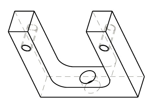
As you can see, the dashed hidden lines are well displayed and are BEHIND the black solid lines that describe the shape of the object.
If you modify the plot_linestyle_scale parameter, the size of the hidden line changes. Here is what happens when I change the value from 3 (previous picture) to 1 (next picture).
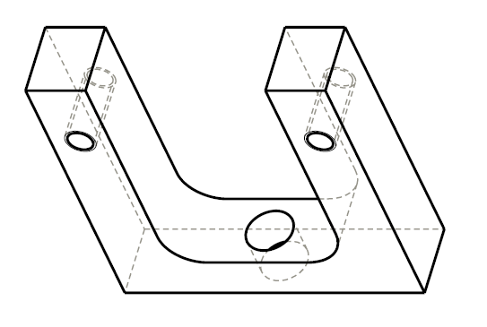
Now the hidden lines appear with smaller elements.
With this method, all is ok ![]() .
.
2) Click on the SaveAs PDF button in the toolbar :

Here is what I obtain :
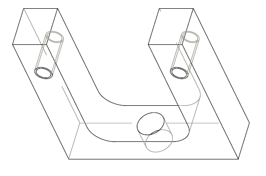
As you can see, the dashed hidden lines have very long elements (they seem to be solid) and, if you look carefully, they appear IN FRONT of the black solid lines, in the same way as already described in the thread http://communities.ptc.com/message/158760. The black solid lines are also thinner than with method 1.
If you modify the value of "plot_linestyle_scale", there is NO modification.
In other forums where this problem of hidden lines style is described, people confuse the two ways to get the PDF and say : modify the "plot_linestyle_scale" to get your result...
As I said, my question is : How do I get a good display of the hidden lines on PDF files with the SaveAs PDF command ???
More generally :
How do I modify the appearance of the drawings processed with the "SaveAs PDF" command ?
For technical reasons, I need to use the method number 2. So, please, don't say "Sylvain, use method 1" ![]() .
.
Thread http://communities.ptc.com/message/158760 could not help me, as it uses File --> Print method.
I use ProE WildFire 4.0
Thank you !
This thread is inactive and closed by the PTC Community Management Team. If you would like to provide a reply and re-open this thread, please notify the moderator and reference the thread. You may also use "Start a topic" button to ask a new question. Please be sure to include what version of the PTC product you are using so another community member knowledgeable about your version may be able to assist.
Solved! Go to Solution.
Accepted Solutions
- Mark as New
- Bookmark
- Subscribe
- Mute
- Subscribe to RSS Feed
- Permalink
- Notify Moderator
hi Sylvain,
This is my new *.pnt file:
! pen 1 for white (visible geometry, curve, quilts)
! pen 2 for yellow (spline surface grid)
! pen 3 for gray (hidden geometry)
! pen 4 for red (dimension lines, leaders, axes and centerlines, balloons, x-hatching)
! pen 5 for green (sheet metal color entities)
! pen 6 for cyan (sketcher section entities)
! pen 7 for dark gray (toggled sections, grayed dimensions and texts, dimmed tangent edges)
! pen 8 for blue (spline surface grid)
pen 1 thickness .05 cm; color 0 0 0
pen 2 thickness .025 cm; color 0 0 0
pen 3 color 0.0 0.0 0.0; pattern .2 .1 cm; thickness 0.025 cm; half_tone_color
pen 4 color 1.0 0.0 0.0; thickness 0.025 cm; letter_color
pen 5 thickness .05 cm; color 0 0 0
pen 6 pattern .2 .2 cm; thickness .025 cm; color 0 0 0
pen 7 thickness .025 cm; color 0 0 0
pen 8 thickness .025 cm; color 0 0 0
Notice that i switched pen 2 and pen 4 notes. This table.pnt does red dimension lines etc.
I've found few options for config.pro related to printing:
use_software_linefonts
- I have this one set to no, couldn't see any difference in the change of this option
use_8_plotter_pens
- didn't quite figure out what does this one do but I have it set to yes to use all 8 pens
plot_linestyle_scale
- this one can be of a value 1 or more for shorter dashes in hidden lines
- if you put pattern command in your *.pnt file then this command has no effect
Well this simply means that you can change the length of the dashes. But about the gray hidden lines always being above black geometry lines I don't really know. Guess the only choice for you is to use black hidden lines as well.
You get a vectorized graphic while exporting to pdf and for some reason the pen 1 is always written first to the pdf before pen 3, Strange is that pen 1 is written after pen 4.
- Mark as New
- Bookmark
- Subscribe
- Mute
- Subscribe to RSS Feed
- Permalink
- Notify Moderator
I realize this probably won't help you out, but I thought that I would post anyway. I noticed you said you were using WF 4.0. We are on 5.0 here and I tried to print and PDF and do a save as PDF and could not tell a difference between the two files. Again sorry that I don't have the answer, but thought It may be worth noting.
-Greg
- Mark as New
- Bookmark
- Subscribe
- Mute
- Subscribe to RSS Feed
- Permalink
- Notify Moderator
Thank you Greg
I don't think it is a problem of version. I think that your ProE is correctly configured. It seems strange to believe that this fundamental functionality (to show hidden lines on a PDF file) was not included in the previous versions of ProE.
There should be the magical option hidden somewhere that enables to get the same result for both methods of PDF creation...
If not, I do not see the purpose of the SaveAs PDF command ...
Sylvain
- Mark as New
- Bookmark
- Subscribe
- Mute
- Subscribe to RSS Feed
- Permalink
- Notify Moderator
Do you have the following option set? sounds like it could be the culprit if you are using the default value in your config.pro options....
Config Option:
pdf_use_pentable
Data Exchange No - PDF export does not use any
defined pentable changes as would be
applied to plotting the drawing.
Acceptable Values:
yes, no
Default Value:
no
Hope this helps,
-Greg
- Mark as New
- Bookmark
- Subscribe
- Mute
- Subscribe to RSS Feed
- Permalink
- Notify Moderator
Thank you Greg
Unfortunately, modifiying this option does not change the appearance of the drawing.
With or without this option enabled, the drawing remains the same.
Sylvain
- Mark as New
- Bookmark
- Subscribe
- Mute
- Subscribe to RSS Feed
- Permalink
- Notify Moderator
hi Sylvain,
I think you didn't set your pen_table_file option right. Gotta make sure that there are no spaces in your pathname.
See this thread:
http://communities.ptc.com/message/158558
I figured out that the pen_table_file option can't be set in WF5 through Tools ---> Options command like other silimar setup files. You gotta write the path to your *.pnt file manually there.
I think the *.pnt file you create determines the pattern of your hidden and other lines. I didn't test it yet but the *.pnt file i posted in the thread (link above) seems to be working fine.
- Mark as New
- Bookmark
- Subscribe
- Mute
- Subscribe to RSS Feed
- Permalink
- Notify Moderator
Hello Jakub !
Thank you for your help. The situation is now better but not as good as expected. Here is what I obtain :
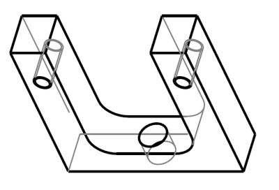
The black line is thicker ![]() . I modified your code like this to get the hidden line with grey color (pen 3) :
. I modified your code like this to get the hidden line with grey color (pen 3) :
pen 3 pattern 0.3 0.3 cm; thickness .025 cm; color 0.5 0.5 0.5
What is strange is that :
1) The hidden line elements are still too big. If I put, for example
pen 3 pattern 0.1 0.1 cm; thickness .025 cm; color 0.5 0.5 0.5
There is no difference !
But if I put
pen 3 pattern 0.1 0.1 cm; thickness .2 cm; color 0.5 0.5 0.5
I get :
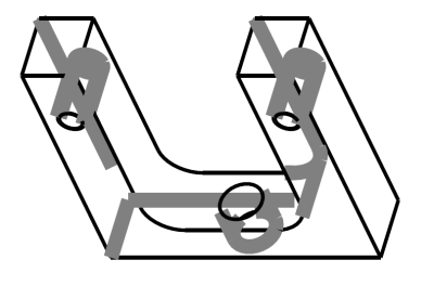
The thickness parameter works !
2) The hidden lines are still in front of the black solid lines (which is clearly the case on the above picture ...). If they are hidden, they should be behind ... ![]()
I think other options need to be set, but, thank you Jakub, this was a big step !
- Mark as New
- Bookmark
- Subscribe
- Mute
- Subscribe to RSS Feed
- Permalink
- Notify Moderator
hi Sylvain,
This is my new *.pnt file:
! pen 1 for white (visible geometry, curve, quilts)
! pen 2 for yellow (spline surface grid)
! pen 3 for gray (hidden geometry)
! pen 4 for red (dimension lines, leaders, axes and centerlines, balloons, x-hatching)
! pen 5 for green (sheet metal color entities)
! pen 6 for cyan (sketcher section entities)
! pen 7 for dark gray (toggled sections, grayed dimensions and texts, dimmed tangent edges)
! pen 8 for blue (spline surface grid)
pen 1 thickness .05 cm; color 0 0 0
pen 2 thickness .025 cm; color 0 0 0
pen 3 color 0.0 0.0 0.0; pattern .2 .1 cm; thickness 0.025 cm; half_tone_color
pen 4 color 1.0 0.0 0.0; thickness 0.025 cm; letter_color
pen 5 thickness .05 cm; color 0 0 0
pen 6 pattern .2 .2 cm; thickness .025 cm; color 0 0 0
pen 7 thickness .025 cm; color 0 0 0
pen 8 thickness .025 cm; color 0 0 0
Notice that i switched pen 2 and pen 4 notes. This table.pnt does red dimension lines etc.
I've found few options for config.pro related to printing:
use_software_linefonts
- I have this one set to no, couldn't see any difference in the change of this option
use_8_plotter_pens
- didn't quite figure out what does this one do but I have it set to yes to use all 8 pens
plot_linestyle_scale
- this one can be of a value 1 or more for shorter dashes in hidden lines
- if you put pattern command in your *.pnt file then this command has no effect
Well this simply means that you can change the length of the dashes. But about the gray hidden lines always being above black geometry lines I don't really know. Guess the only choice for you is to use black hidden lines as well.
You get a vectorized graphic while exporting to pdf and for some reason the pen 1 is always written first to the pdf before pen 3, Strange is that pen 1 is written after pen 4.
- Mark as New
- Bookmark
- Subscribe
- Mute
- Subscribe to RSS Feed
- Permalink
- Notify Moderator
Great Jakub ! You did it ![]() !
!
I now have the hidden lines correctly displayed. Here is the result with your .pnt file :
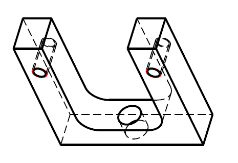
After investigation, the half_tone_color parameter needs to be written to get the dashed lines.
With
pen 3 color 0.0 0.0 0.0; pattern .2 .1 cm; thickness 0.025 cm
it does not work...
With
pen 3 color 0.0 0.0 0.0; pattern .2 .1 cm; thickness 0.025 cm; half_tone_color
It works !
For the problem of hidden lines vs geomtery lines, I will perhaps open a new thread soon. If we look carefully, some hidden lines are behind the geometry lines, while other are in front of the geometry lines... There should be parameters somewhere to define the pen printing order.
Anyway, thanks for all !
- Mark as New
- Bookmark
- Subscribe
- Mute
- Subscribe to RSS Feed
- Permalink
- Notify Moderator
You're welcome, Sylvain.
It was interesting to find at least this out. I am looking forward to see your *.pnt file.
I also have bunch questions about exporting drawings from Pro/E but mostly related to dwg export or about Pro/E drawings by itself. Will start shooting them propably next week in new topics ofc.
- Mark as New
- Bookmark
- Subscribe
- Mute
- Subscribe to RSS Feed
- Permalink
- Notify Moderator
Has anyone figured out a solution to this problem, RE: I want to utilze the SAVE AS>PDF without the hidden lines obscuring visible solid lines and particularly call-outs or annotations (and avoid the printing with a PDF printer method)?
I am having the same issue the OP mentions however have not found a work around. Please see the image below. The call out arrow as well as the visidble geometry are clearly behind the hidden lines whereas they should be in front. Using a PDF printer resolves the issue however this method is cumbersome and time consuming. I have configured my pen table correctly and I don't believe that is an issue.
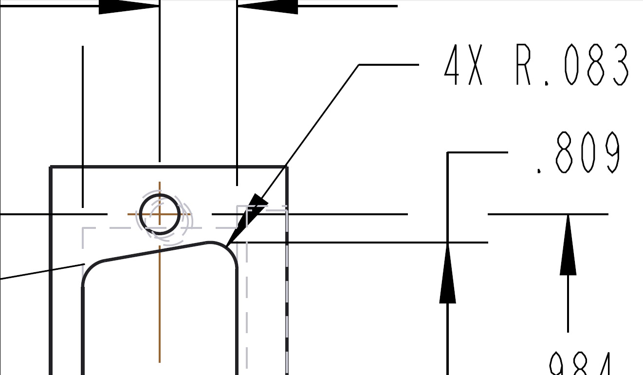
Thanks in advance for any help!!
- Mark as New
- Bookmark
- Subscribe
- Mute
- Subscribe to RSS Feed
- Permalink
- Notify Moderator
If you used black for the hidden lines the error would go unnoticed.
This is most likely the 'fix' seen in the sequence above.
Probably it is due to PTC performing the HLR based on a front-to-back evaluation for hidden lines, so there is no fix on the user side.
PTC would have to gather all the hidden lines and plot them first or evaluate from back-to-front.
- Mark as New
- Bookmark
- Subscribe
- Mute
- Subscribe to RSS Feed
- Permalink
- Notify Moderator
Thanks for the reply however internal drafting standards dictate that all hidden lines must be gray for reading clarification so this is not a viable option for me.
- Mark as New
- Bookmark
- Subscribe
- Mute
- Subscribe to RSS Feed
- Permalink
- Notify Moderator
Hello Andrew,
The problem propably lies in the interface_quality config.pro option. While I don't recommend setting this option to lower number than 2, which means 2 or 3 is fine, for the purpose of showing the PDF graphics right, it should be set to 0.
I think there is a way to switch interface_quality from say 2 to 0 and back if you are on Creo Parametric 2.0. That means you could possibly create a single mapkey for PDF export, and also iconize it if you wish.
Try if interface_quality 0 affects your PDFs.
- Mark as New
- Bookmark
- Subscribe
- Mute
- Subscribe to RSS Feed
- Permalink
- Notify Moderator
Hi Jakub,
You seem to have hit the nail on the head regarding the config.pro option. It is interesting however that setting interface_quality to 0, 2, or 3 does not resolve the issue whilst setting it to 1 does. Is this option only for plotting purposes? If so I am working exclusively from pdf documents and I presume I could set it to 1 permanently and not worry about generating any mapkey.
Otherwise, I am working on Creo Parametric 2.0 build M100 and would like to learn more about utilizing a mapkey and possibly iconizing it. In spite of working on Creo for about a year and a half now, I had never heard of mapkeys and upon doing some research found the following helpful links:
http://en.wikibooks.org/wiki/Pro_Engineer/Mapkeys
http://communities.ptc.com/thread/39882
I will do some more research and potentially utilize this functionality in the future.
Thanks for the help!!!
- Mark as New
- Bookmark
- Subscribe
- Mute
- Subscribe to RSS Feed
- Permalink
- Notify Moderator
Just to add a brief update….
It seems as though something very funny is going on here. From a fresh start in Creo, if I follow the procedure mentioned in my previous post it does not work, ie: the hidden lines are still on top of solid lines, call-outs, annotations etc. Now if I follow the same procedure, ie: with interface_quality set to 1, and choose FILE>SAVE AS then selecting pdf from the drop down menu at the bottom, and when the pdf export settings screen comes up I go to the content tab and at the bottom under the compatibility option I choose PDF/A-1, I get my desired output where the hidden lines are BELOW everything. Without closing Creo I can then go on to resave the file, overwriting the existing file, however this time instead of choosing the PDF/A-1 compatibility I use the standard PDF, it will function correctly. ![]()
If I then try and change the interface_quality setting to some of the other options the hidden lines will once again end up on top of everything. So I just leave it set as 1 for the time being. I have never created PDF/A files for drawings before and don’t really understand exactly what is going on here.
- Mark as New
- Bookmark
- Subscribe
- Mute
- Subscribe to RSS Feed
- Permalink
- Notify Moderator
Ah yes, so it's 1 and not 0 then. Could you post the contents your pnt file here? Mine is still set as you can see in the post up above, that means I print in all black.
Well, as for the mapkey including the interface quality change. First you need to put the following line into your config.pro:
content_favorites_page_options interface_quality
Then also add the following mapkey into your config.pro as well:
mapkey -pdf @MAPKEY_LABELExport drawing to PDF;\
mapkey(continued) ~ Select `main_dlg_cur` `appl_casc`;~ Close `main_dlg_cur` `appl_casc`;\
mapkey(continued) ~ Command `ProCmdRibbonOptionsDlg` ;\
mapkey(continued) ~ FocusIn `ribbon_options_dialog` \
mapkey(continued) `favorites_layouts.InputPanel_ip.INTERFACE_QUALITY`;\
mapkey(continued) ~ Update `ribbon_options_dialog` \
mapkey(continued) `favorites_layouts.InputPanel_ip.INTERFACE_QUALITY` `1`;\
mapkey(continued) ~ Activate `ribbon_options_dialog` \
mapkey(continued) `favorites_layouts.InputPanel_ip.INTERFACE_QUALITY`;\
mapkey(continued) ~ FocusOut `ribbon_options_dialog` \
mapkey(continued) `favorites_layouts.InputPanel_ip.INTERFACE_QUALITY`;\
mapkey(continued) ~ Activate `ribbon_options_dialog` `OkPshBtn`;\
mapkey(continued) ~ FocusIn `UITools Msg Dialog Future` `no`;\
mapkey(continued) ~ Activate `UITools Msg Dialog Future` `no`;\
mapkey(continued) ~ Close `main_dlg_cur` `appl_casc`;~ Command `ProCmdExportPreview` ;\
mapkey(continued) ~ Command `ProCmdDwgPubSetDeliverable` `DXF`;\
mapkey(continued) ~ Command `ProCmdDwgPubSetDeliverable` `PDF`;\
mapkey(continued) ~ Command `ProCmdDwgPubSettings` ;\
mapkey(continued) ~ Select `intf_profile` `pdf_export.pdf_lines` 1 `pdf_hidden_solid`;\
mapkey(continued) ~ Select `intf_profile` `pdf_export.pdf_lines` 1 `pdf_hidden_dashed`;\
mapkey(continued) ~ Activate `intf_profile` `pdf_export.pdf_pentable` 0;\
mapkey(continued) ~ Activate `intf_profile` `pdf_export.pdf_pentable` 1;\
mapkey(continued) ~ Activate `intf_profile` `pdf_export.pdf_launch_viewer` 0;\
mapkey(continued) ~ Select `intf_profile` `pdf_export.PDFMainTab` 1 `pdf_export.PDFContent`;\
mapkey(continued) ~ Select `intf_profile` `pdf_export.pdf_font_stroke` 1 `pdf_stroke_all`;\
mapkey(continued) ~ Select `intf_profile` `pdf_export.pdf_font_stroke` 1 `pdf_stroke_none`;\
mapkey(continued) ~ Activate `intf_profile` `pdf_export.pdf_hyperlinks` 0;\
mapkey(continued) ~ Activate `intf_profile` `OkPshBtn`;~ Command `ProCmdDwgPubExport` ;\
mapkey(continued) ~ Activate `file_saveas` `OK`;~ Activate `UI Message Dialog` `ok`;\
mapkey(continued) ~ Command `ProCmdDwgPubCloseExportPvw` ;~ Select `main_dlg_cur` `appl_casc`;\
mapkey(continued) ~ Close `main_dlg_cur` `appl_casc`;~ Command `ProCmdRibbonOptionsDlg` ;\
mapkey(continued) ~ FocusIn `ribbon_options_dialog` \
mapkey(continued) `favorites_layouts.InputPanel_ip.INTERFACE_QUALITY`;\
mapkey(continued) ~ Update `ribbon_options_dialog` \
mapkey(continued) `favorites_layouts.InputPanel_ip.INTERFACE_QUALITY` `2`;\
mapkey(continued) ~ FocusOut `ribbon_options_dialog` \
mapkey(continued) `favorites_layouts.InputPanel_ip.INTERFACE_QUALITY`;\
mapkey(continued) ~ Activate `ribbon_options_dialog` `OkPshBtn`;
Restart Creo, open up a drawing, and then just type pdf into the search field, you will see search result like on the following picture.
You can click onto the command to make it run from there, and also you can just add the icon anywhere on your ribbon via options menu.
Interface quality affects other filetypes as well, not just PDFs.
- Mark as New
- Bookmark
- Subscribe
- Mute
- Subscribe to RSS Feed
- Permalink
- Notify Moderator
Assuming you are referring to my pen table, it is attached. I am only working in gray and black with two line thicknesses however as can be seen form the image above, centerlines and axes appear in a reddish color which I don't mind so much and assuming this setting has been carried over from the default values, I will likely leave it alone. I am follow line guidelines specified within ASME Y14.100 and ASME Y14.5. So far I have not had the necessity to make any additional modifications to my pentable other than what I have for three first pens in order to maintain these line conventions.
Thanks for the info regarding mapkeys! I will consider it in the future when I have some spare time.
You stated, "Interface quality affects other filetypes as well, not just PDFs."
What other file types should I be concerned about?
- Mark as New
- Bookmark
- Subscribe
- Mute
- Subscribe to RSS Feed
- Permalink
- Notify Moderator
PDF/A is the Archive suggested practice. The main requirement is the file have no external references, such as referring to fonts that are supposed to be loaded by the PDF processor; instead fonts are to be embedded.
It's likely there is some other flaw that has nothing really to do with PDF/A, but the group that wrote the PDF/A part fixed what the other group didn't.
From Wikipedia on PDF/A
- Audio and video content is forbidden.
- JavaScript and executable file launches are forbidden.
- All fonts must be embedded and also must be legally embeddable for unlimited, universal rendering. This also applies to the so-called PostScript standard fonts such as Times or Helvetica.
- Colorspaces specified in a device-independent manner.
- Encryption is forbidden.
- Use of standards-based metadata is mandated.
- External content references are forbidden.
- LZW and JPEG2000 image compressions are forbidden in PDF/A-1, but JPEG 2000 compression is allowed in PDF/A-2.
- Transparent objects and layers (Optional Content Groups) are forbidden in PDF/A-1, but they are supported in PDF/A-2.
- Provisions for digital signatures in accordance with the PAdES (PDF Advanced Electronic Signatures) standard are supported in PDF/A-2.
- Embedded files are forbidden in PDF/A-1, but PDF/A-2 offers the possibility to embed PDF/A files, allowing archiving of sets of PDF/A documents in a single file. PDF/A-3 allows embedding of any file format such as XML, CAD and others into PDF/A as complete archived objects.
- The use of XML-based XML Forms Architecture (XFA) forms is forbidden in PDF/A-2. XFA is also not allowed in PDF/A-1, because it is used in PDF specification since PDF 1.5. (The preservation of the XFA form data in a PDF/A-2 file may be done by moving from XFA key to the Names tree that itself is the value of the XFAResources key of the Names dictionary of the document catalog dictionary.)
- Interactive PDF forms - Every form field shall have an appearance dictionary associated with the field's data in PDF/A. The appearance dictionary shall be used when rendering the field, the value of a form field shall not be used.


