- Community
- Creo+ and Creo Parametric
- 3D Part & Assembly Design
- Re: How can I change how dimension lines appear?
- Subscribe to RSS Feed
- Mark Topic as New
- Mark Topic as Read
- Float this Topic for Current User
- Bookmark
- Subscribe
- Mute
- Printer Friendly Page
How can I change how dimension lines appear?
- Mark as New
- Bookmark
- Subscribe
- Mute
- Subscribe to RSS Feed
- Permalink
- Notify Moderator
How can I change how dimension lines appear?
Hi,
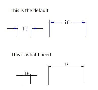
So I have this problem with how the dimension lines appear. With small dimensions when the arrows are outside of the witness lines there is no line to connect the witness lines. This becomes quite messy when having a lot of small dimensions. I would like to change the dimension style so that the witness lines are always connected.
Does anyone know how to change this? I'm using creo 2.0.
Thanks.

Solved! Go to Solution.
- Labels:
-
2D Drawing
Accepted Solutions
- Mark as New
- Bookmark
- Subscribe
- Mute
- Subscribe to RSS Feed
- Permalink
- Notify Moderator
There is a drawing setup option under FILE PREPARE DRAWING PROPERTIES detail options CHANGE
default_lindim_text_orientation
use the value parallel_to_and_above_leader
- Mark as New
- Bookmark
- Subscribe
- Mute
- Subscribe to RSS Feed
- Permalink
- Notify Moderator
There is a drawing setup option under FILE PREPARE DRAWING PROPERTIES detail options CHANGE
default_lindim_text_orientation
use the value parallel_to_and_above_leader
- Mark as New
- Bookmark
- Subscribe
- Mute
- Subscribe to RSS Feed
- Permalink
- Notify Moderator
Noting that you appear to have ASME-style dimension cosmetics, and are interested in ISO/JIS/DIN style, you may also wish to look at the various options that differ between the default prodetail.dtl (ASME) and iso.dtl / din.dtl / etc. Having figured the set of values that work for the standard you want, use this detail setup as your default (in your drawing template and/or the config 'drawing_setup_file'.
- Mark as New
- Bookmark
- Subscribe
- Mute
- Subscribe to RSS Feed
- Permalink
- Notify Moderator
Solved, thanks for replies.


