Community Tip - Have a PTC product question you need answered fast? Chances are someone has asked it before. Learn about the community search. X
- Community
- Creo+ and Creo Parametric
- 3D Part & Assembly Design
- Re: How do you drive a Creo Parametric Part (.prt)...
- Subscribe to RSS Feed
- Mark Topic as New
- Mark Topic as Read
- Float this Topic for Current User
- Bookmark
- Subscribe
- Mute
- Printer Friendly Page
How do you drive a Creo Parametric Part (.prt) parameters/attributes from file using a text file? Pro Program? Something else?
- Mark as New
- Bookmark
- Subscribe
- Mute
- Subscribe to RSS Feed
- Permalink
- Notify Moderator
How do you drive a Creo Parametric Part (.prt) parameters/attributes from file using a text file? Pro Program? Something else?
We have a parameter/attribute driven .prt template that we want to use to create new models based off a text file.
I looked at Pro/Program to do this but couldn’t find a Parameter/Attribute section. I don’t think it would be a problem if the above were buried in the Pro-Program text file and it just replace the entire file, but I cannot even find which section this would go in.
E.g. To use a simple example, let’s say we have a cylinder with 2 parameters, which drive the dimensions:
1) Diameter “Dia1”
2) Length “L1”
We then have relations that drive these 2 parameters that look something like this:
1) d1=dia1
2) d2=L1
We would like to have a text file that contains actual dimensions for “dia1” and “L1” to be able to create a model based off the above template and the contents of the text file such as:
Dia1=0.25”
L1=2.00”
Can Pro/Program be used for this? Is there another way? Is there a better way? How can this be done?
"When you reward an activity, you get more of it!"
- Labels:
-
General
- Mark as New
- Bookmark
- Subscribe
- Mute
- Subscribe to RSS Feed
- Permalink
- Notify Moderator
I've only ever done this using trail files or mapkeys to modify existing part. I usually use VBA/Excel to generate the files. Pro/Program doesn't do this though some sort of Excel analysis might.
What is the workflow you expect to use if you had an ideal situation?
- Mark as New
- Bookmark
- Subscribe
- Mute
- Subscribe to RSS Feed
- Permalink
- Notify Moderator
Expected use is:
User exports a text file containing driving parameters generated from a 3rd party program.
Mapkey to create the part from a template after the user references that part file with the driving parameters.
So the part of interest is a spring and we want to create the model based off of the spring design software output.
"When you reward an activity, you get more of it!"
- Mark as New
- Bookmark
- Subscribe
- Mute
- Subscribe to RSS Feed
- Permalink
- Notify Moderator
Hi Lawrence,
Your focus is "We have a parameter / attribute driven .prt template that we want to use to create new models based off a text file."
There are many ways to enter part parameter values and drive the part, but a simple way is from the relation.
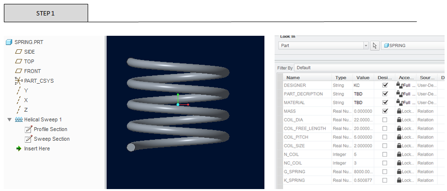
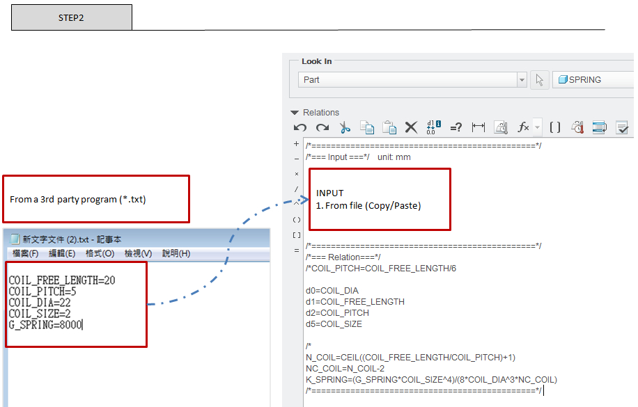
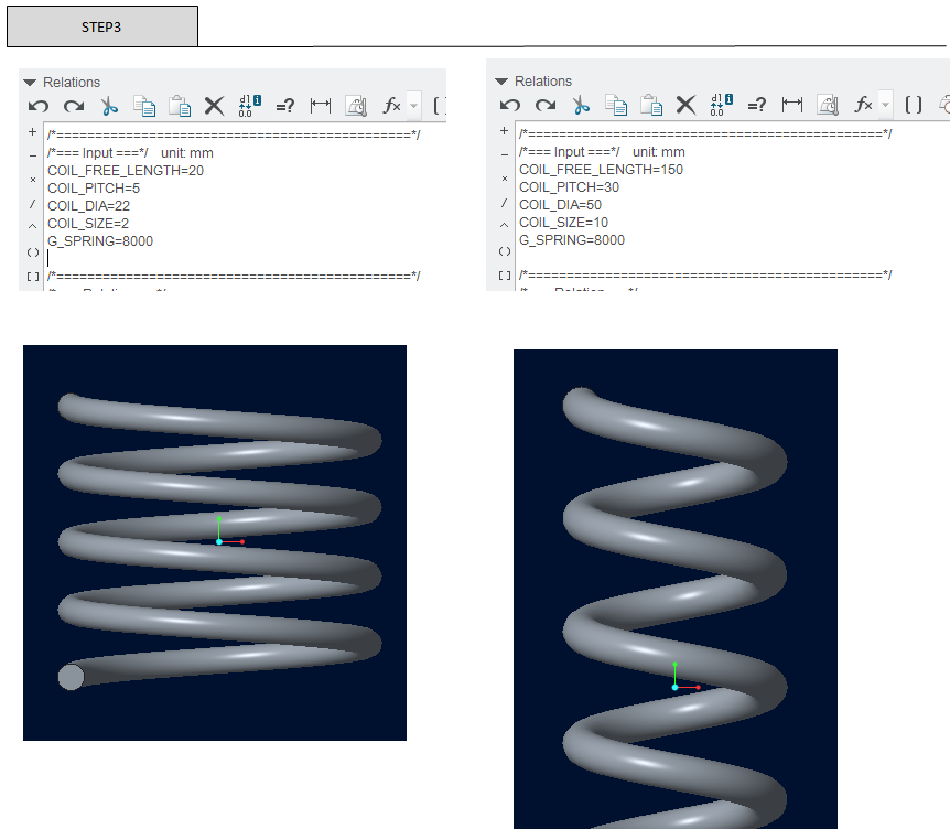
Your idea is to go from a text file => Pro/Program => Part (* .prt), maybe change the workflow process to a text file =>Relation=> Part (* .prt).
Show an example as below,hope it helps you.
My English is pretty limited, please don't mind.
KC


- Mark as New
- Bookmark
- Subscribe
- Mute
- Subscribe to RSS Feed
- Permalink
- Notify Moderator
Hi,
yes, you can use Pro/PROGRAM.
Pro/PROGRAM example:
VERSION 2.0
REVNUM 86
LISTING FOR PART PRT0001
INPUT
VYSKA NUMBER
END INPUT
RELATIONS
D3=VYSKA
END RELATIONS
... and so on ...
When you regenerate a part, you use Read File command and enter file name (unfortunatelly you cannot browse folders...).
Example of myfile.txt contents
VYSKA=123
MH
Martin Hanák
- Mark as New
- Bookmark
- Subscribe
- Mute
- Subscribe to RSS Feed
- Permalink
- Notify Moderator
We use Automation Gateway as well to handle parameters in models. It is easy to use, but it is not for free.
- Mark as New
- Bookmark
- Subscribe
- Mute
- Subscribe to RSS Feed
- Permalink
- Notify Moderator
I think I can help you on this because that's the thing I am currently doing for my company.
Use Excel VBA and Mapkey in Creo, see example below:
Sub writeParameters()
Dim filePath, filePath1 As String, textData As String, fileNo As Integer
Dim FromPath, ToPath As String
Dim dataP01, dataP02, dataP03, dataP04, dsgDate, Ldate As String
Dim FSO As Object
Dim wbCnfgr As Workbook
filePath = "full path and name of the text file which you write parameters to" (Eg, "C:\AutoDesign\AutoDsg_D\A999-2740\03 CADFiles\15-X\xxx.txt")
dataP01 = Range("A1")+ "=" +Range("B1") '(A1=parameter name , B1= parameter value on your worksheet)
dataP02 = Range("A2")+ "=" +Range("B2")
dataP03 = Range("A3")+ "=" +Range("B3")
dataP04 = Range("A4")+ "=" +Range("B4")
Ldate = Date
dsgDate = "/*Designed by ...on " + Ldate
fileNo = FreeFile 'Get first free file number
Open filePath For Append As #fileNo
Print #fileNo, dsgDate
Print #fileNo, dataP01
Print #fileNo, dataP02
Print #fileNo, dataP03
Print #fileNo, dataP04
Close #fileNo
'End If
End Sub
And in Creo you just create a makey to import the text file to your relation.

- Mark as New
- Bookmark
- Subscribe
- Mute
- Subscribe to RSS Feed
- Permalink
- Notify Moderator
Two thoughts. First, we have done something similar in the past to what KC Ai is suggesting. We created a bunch of feature parameters inside a stable (but never looked) in feature (one of the datum planes at the top of the model tree.) We then created a mapkey to automatically browse to a folder and wait for us to pick a file, and then copy the contents of the file into this feature as feature relations. Relations were added to the other features in the model so they referenced these feature parameters. It was easy enough to build an Excel file that could directly generate the exact relations statements needed (we would copy them to a text file before importing.)
A second idea might be to use Nitro-CELL. There is a free version available. Definitely worth taking a look at.
- Mark as New
- Bookmark
- Subscribe
- Mute
- Subscribe to RSS Feed
- Permalink
- Notify Moderator
Here's the method we have been using for the past 10 years:
Microsoft Excel drives our 3D models. Basicly its a combination of the solutions by Martin Hanak (CREO side) and Changxing Lin (EXCEL side)
EXCEL
1) Create an Excel spreadsheet to calculate the values of the parameters which drive your part/assembly. Make the Excel spreadsheet as fancy as you like.
2) Use one sheet of that Excel spreadsheet to hold all the parameters (name of parameter in column A, value in column B)
3) Create an (ActiveX) button and write a small Excel VBA macro which will export all the parameters and their values to a text-file.
We use the exact same text-file over and over again, overwriting the contents when we generate something new. For example: "c:\temp\my_creo_parameters.txt"
CREO
1) Use INPUT parameters
Each PART and ASSEMBLY are driven by INPUT parameters. You can use STRING, YES_NO and NUMBER.
2) Use EXECUTE statements
Use the EXECUTE statement in your assembly to drive the INPUT parameters of any PART and/or sub ASSEMBLY
3) Use Mapkeys
As soon as a part or assembly contains INPUT parameters, you will get the option to use "Read file" when regenerating that part/assembly. Create a mapkey that will do "Edit" --> "Regenerate"--> "Read File" --> "c:\temp\my_creo_parameters.txt". You can also assign a mapkey to a button.
FINAL WORKFLOW
1) Open the Excel spreadsheet, configure your design, hit the button in Excel to generate the "my_creo_parameters.txt"
2) Open your design (part/assemby) in CREO, hit the button which executes the mapkey to read the values from "my_creo_parameters.txt"
P.s. If you are wondering how many parameters you can use...our biggest model uses 1264 input parameters at top-level.
HTH
- Mark as New
- Bookmark
- Subscribe
- Mute
- Subscribe to RSS Feed
- Permalink
- Notify Moderator
- Mark as New
- Bookmark
- Subscribe
- Mute
- Subscribe to RSS Feed
- Permalink
- Notify Moderator
Hi, Teun,
What the EXECUTE statements are doing exactly? That's the only part I didn't understand.
Thank you,
Nic.
PS. Do you have any experience with Drawing Program? I opened a new question about that here:
- Mark as New
- Bookmark
- Subscribe
- Mute
- Subscribe to RSS Feed
- Permalink
- Notify Moderator
EXECUTE
This is for assemblies to link assy input variables to program variables in assembly components.
EXECUTE {PART}/{ASSY } name or variable
input variable of design at next lower level = expression
input variable.....
END EXECUTE
Only reaches one level, but that level can domino to the next.
Can be used with IF-ELSE-ENDIF
For example
Let's say we have an assembly with a part called "MyComponent".
Assembly (asm)
| MyComponent (prt)
The "MyComponent" has an INPUT parameter called "MY_LENGTH" which is a NUMBER.
Inside the pro/program of te assemby, after the RELATIONS, you can write
EXECUTE PART MyComponent
MY_LENGTH = 100
END EXECUTE
This will set the parameter "MY_LENGTH" of "MyComponent" to 100.
You can replace the 100 with a parameter of your own.
As for the DRAWING PROGRAM.
You create DRAWING STATES in the drawing, then active those DRAWING STATES with the drawing program.
A DRAWING STATE can hide/show dimenions or views for example.
IF HIDE_SECTION_VIEW == YES
SET STATE DONT_SHOW_SECTION_VIEW
ENDIF
HIDE_SECTION_VIEW is a parameter from the part/assembly
DONT_SHOW_SECTION_VIEW is a DRAWING STATE created in the drawing (which hides the section view)
- Mark as New
- Bookmark
- Subscribe
- Mute
- Subscribe to RSS Feed
- Permalink
- Notify Moderator
Wow, Teun!! You're a gold mine! Thank you.
May I dare two additional questions:
1. The {ASSY } in the EXECUTE is refered to a sub-assy in the main assy, I suppose, right? As you said it only goes down one level, I won't be able to EXECUTE an input form a part in the sub-assy of my assy. This is what I understood from your explanation. But that are ways to make it propagate further if you need.
2. In Drawing Program is it possible that several states are "active" at the same time?
For example:
I have an assy with:
- four languages for the drawing to choose from which I manage in Drawing Program with a block of view states called /* Language for example
- I could have from 0 to 4 holes for my assy and I manage this in Drawing program with a block of view states called /* Holes for examples
- I could have or not a Groove with or without chamfer and I manage this with a block called /*Groove and Chamfer for example
And all this are parameters in the INPUT block in Pro/PROGRAM.
How it works?
-English Set State English
-One Hole Set State One_Hole
-Groove without Chamfer Set State Groove_without_Chamfer
and there will be one over another.
And if I go the assy and change just the language parameter to French, the drawing will update only the language?
Something like that?
I am sorry for the over detailed questions, but for Drawing Program I couldn't find a Tutorial as I have for Pro/Program
Thank you very much again,
Nic.
- Mark as New
- Bookmark
- Subscribe
- Mute
- Subscribe to RSS Feed
- Permalink
- Notify Moderator
1. Correct.
2. Yes, that should be possible
Please see attachment for an example
- Mark as New
- Bookmark
- Subscribe
- Mute
- Subscribe to RSS Feed
- Permalink
- Notify Moderator
Yes!! Exactly! Thank you!
And I was thinking that I have to do a separate state for the holes too. But it's enough to manage the states with the pattern.
Is it possible to insert a custom symbol (the one in Annotate-Symbol-Custom Symbol) in a View State? All I could find in the Help was this:
To create detail items such as dimensions, notes, and balloon notes in a drawing state, choose Create from the DWG COMMANDS menu that appears when you click Tools > Drawing Program > Define States > Create State > Record Cmds. Items that you create in one state are not visible in any other state or outside of the drawing program
which doesn't refer to Symbols but Dimensions, Notes, Balloons.
I mean, instead of your example of "THIS IS AN ENGLISH NOTE" note to have a Custom Symbol for every language used free ("this is a note" symbol) or attached to a dimension/surface ("this is the oil groove" attached to the dimension of the groove "36" or an edge of it. So, no groove-no symbol, changed language- changed language of the symbol)
Nic.
- Mark as New
- Bookmark
- Subscribe
- Mute
- Subscribe to RSS Feed
- Permalink
- Notify Moderator
Hi Teun,
I have downloaded nalexandru.zip file you have attached for the given reference. I am looking changed value by entering through program>Edit Design> Yes> Enter value for Length. Model is updating but drawing file not.
Can you please guide me for that.
Thanks in advance!!
- Mark as New
- Bookmark
- Subscribe
- Mute
- Subscribe to RSS Feed
- Permalink
- Notify Moderator
Hi, Anu,
Did you updated from the drawing file? Maybe you should refresh the views?
Cheers,
Nic.
- Mark as New
- Bookmark
- Subscribe
- Mute
- Subscribe to RSS Feed
- Permalink
- Notify Moderator
Impressive... like your idea
- Mark as New
- Bookmark
- Subscribe
- Mute
- Subscribe to RSS Feed
- Permalink
- Notify Moderator
Although not as detailed an answer as some of the previous ones, please take a look into External Analysis. I have used it in the past to successfully read in customers' pre-existing algorithms/calculation results. I usually modify the program to produce repeatable output (csv works well), then read the results into a part/assembly, pulling out whatever its needed. The results are fairly easily accessed from the analysis feature. Depending on your needs, the analysis feature can exist anywhere in the model tree where you can hopefully avoid multiple regenerations.
- Mark as New
- Bookmark
- Subscribe
- Mute
- Subscribe to RSS Feed
- Permalink
- Notify Moderator
You could also use an external program like Model Processor (free Guest version). It has an action to solve specfically this topic. http://mp.inneo.com , register , download , use. (only >= WF 4, better >= Creo 2.0) this shouldn't be seen as advertising so the guest mode is free and should solve the task.
Br,
Eike


