
Turn on suggestions
Auto-suggest helps you quickly narrow down your search results by suggesting possible matches as you type.
Showing results for
Please log in to access translation
Turn on suggestions
Auto-suggest helps you quickly narrow down your search results by suggesting possible matches as you type.
Showing results for
Community Tip - Need to share some code when posting a question or reply? Make sure to use the "Insert code sample" menu option. Learn more! X
- Community
- Creo+ and Creo Parametric
- 3D Part & Assembly Design
- Re: How do you manage springs
Translate the entire conversation x
Please log in to access translation
Options
- Subscribe to RSS Feed
- Mark Topic as New
- Mark Topic as Read
- Float this Topic for Current User
- Bookmark
- Subscribe
- Mute
- Printer Friendly Page
How do you manage springs
Jul 26, 2013
01:05 PM
- Mark as New
- Bookmark
- Subscribe
- Mute
- Subscribe to RSS Feed
- Permalink
- Notify Moderator
Please log in to access translation
Jul 26, 2013
01:05 PM
How do you manage springs
I need some tips for good model management. This is a challenge I know I can work around, but I would like to know how you take on this challenge.
Also please confirm if you actually use your technique in production or if this is a what you consider your best take on the subject.
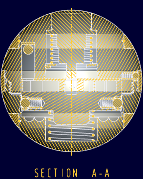
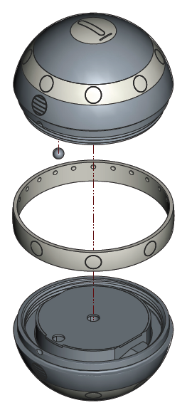
I am working on a model and drawing for the ISIS I orb. It has a half dozen springs in the assembly and several levels of subassembly.
I have all the springs modeled as free-length (suppressed in the model) and as-used length (separate model).
The cross section on the drawing and in the model looks -perfect-...(!)
... and then I embark on the exploded view realizing I want to swap out the sprung springs for the unsprung springs.
My first instinct is to add the unsprung springs to the drawing so I can delete the suppressed components in the model (1) PDM BOM accuracy consideration) (2) file export consideration)
My second instinct is to manipulate the two versions of the springs on layers (...never like layers in Pro|E; better in Creo)
But there are inklings that says we can make this challenge work more fluently.
- What comes to mind is use of family tables for the springs but this would mean extra parts in the model (doesn't solve BOM/PDM issue)
- Combined states should be able to solve this dilemma but the master rep would have both lengths shown.
- Flexible components cannot change length from one view to another; not much help.
- I could take meds for my OCD and get on with life.
There are two situations also under consideration but are less obvious to a solution but worth considering.
- The assembly model exploded view -should- swap out the sprung springs with unsprung springs when viewing the exploded view. This is a candidate for view states.
- Also, detent springs actually have 3 states; unsprung (for part drawings), installed (for subassembly drawings), and actuated (for top level drawing).
Besides the coil springs, there are also 3 other components that have a sprung and unsprung state. The total is 10 flexy components in a ~33 component assembly.
How would you tackle this challenge if your employer was a stickler for accuracy?
This thread is inactive and closed by the PTC Community Management Team. If you would like to provide a reply and re-open this thread, please notify the moderator and reference the thread. You may also use "Start a topic" button to ask a new question. Please be sure to include what version of the PTC product you are using so another community member knowledgeable about your version may be able to assist.
Labels:
- Labels:
-
2D Drawing
36 REPLIES 36
Jul 26, 2013
03:39 PM
- Mark as New
- Bookmark
- Subscribe
- Mute
- Subscribe to RSS Feed
- Permalink
- Notify Moderator
Please log in to access translation
Jul 26, 2013
03:39 PM
Check you personal e-mail. 
Jul 26, 2013
05:33 PM
- Mark as New
- Bookmark
- Subscribe
- Mute
- Subscribe to RSS Feed
- Permalink
- Notify Moderator
Please log in to access translation
Jul 26, 2013
05:33 PM
Hi Tom.
If I understand you correctly then this is a candidate for Family Tables.
You would have a high level FT of your assembly with an instance for the Exploded and Non-exploded states.
This allows you to have each sping state (in your case separate models but could be FT themselves) and you have each high level instance in your drawing and only report your BoM on one of those and therefore be correct.
Seems relatively straightforward but probably means I am missing something.
Oh yes forgot to say have used this technique serveral times over the years.
Regards. Brent
Jul 26, 2013
05:52 PM
- Mark as New
- Bookmark
- Subscribe
- Mute
- Subscribe to RSS Feed
- Permalink
- Notify Moderator
Please log in to access translation
Jul 26, 2013
05:52 PM
Family tables huh. Interesting thought. Haven't used them in the past but this sounds correct.
What will the master model present? Will it include all versions or only that which you specify?
Jul 27, 2013
04:51 AM
- Mark as New
- Bookmark
- Subscribe
- Mute
- Subscribe to RSS Feed
- Permalink
- Notify Moderator
Please log in to access translation
Jul 27, 2013
04:51 AM
Hi Tom.
You can approach this a couple of ways. It is possible to use the Generic (the top level of the Family Table) as the master and have only one instance for the model you want to use for your exploded view. Or you can have the Generic the same as that but have an Instance for each state you want in the drawing. No right answer. The big thing with FT is to do all the manipulation in the Generic. Easy mistake is to do work in an Instance then when you go back into the model some stuff is not how you thought it would be. Do the work in the Generic solves this. When you are ready good tip is to use the check box for verify instances before saving. People who work with FT will be familiar with this but not intuitive for learners.
Lets go with the first method of using the Generic as your master. This means you have your tree just like you do now with the compressed springs and everything in place. Anything else is suppressed if there are extra models such as your uncompressed springs. Make a Family table and add an Instance (call it Exploded if you like) BUT do not add anything yet. Save your model. Now suppress the compressed springs and resume the uncompressed ones. Open the FT dialogue and add these uncompressed parts (tree or model window). Verify the instance. Open the Instance and check that it has the parts you want and if not go back to the Generic model to fix it. Not sure if you make your explode in the instance or the Generic with the uncompressed parts, you will have to try that out. Save the Generic should lock in all the info. Same process for another state.
If you are making a new drawing then add the Generic first with any views you want (assuming you want to use the Exploded Instance for a BoM Table). Then Add the Exploded Instance to the drawing and make sure this model is set. Add your exploded view and do the BoM Table/Balloons. You can set either model to be what use at that time in your drawing but it is easy to get mixed up so best to do everything you want on one model at one time.
I think I would use a FT for the springs themselves rather than extra parts as this would mean only one "part" to manage. Management of the top level FT takes a little more effort in the FT dialogue box but easy enough when you get the the hang of it.
Hope this helps enough as I am away from ProE/Creo at the moment until Monday our time. Also hope that this is not to condescending for you.
Regards, Brent
Jul 27, 2013
05:34 AM
- Mark as New
- Bookmark
- Subscribe
- Mute
- Subscribe to RSS Feed
- Permalink
- Notify Moderator
Please log in to access translation
Jul 27, 2013
05:34 AM
This is very helpful, Brent. As I said before, I am not a big fan of family tables but I need to get the hang of it sometime. Sure enough, when I 1st tried to make a FT at the top level, Creo crashed (Creo 2.0 M040).
I was working on the drawing today and really had a hard time getting the explode lines (offset lines) to behave.
For the time being, I opted for my 1st instinct: to make a next level assembly just to add the unsprung springs. Therefore I ended up with layers to manage the other springs which I can turn off in views. But had I got to it earlier, I could have just omitted them in the simplified reps which I ended up using for the sub-assembly views.
There are some real bugs in the explode routine. I have 3 levels of assemblies and I worked from the bottom to the top level. It was all I could do to manage the explode without things jumping out of place. Almost like you have to wrestle everything into place. Things didn't move together and copy location was just plane freaking out.
So at this moment I am still with multiple files for the springs. The drawing has the "master" assembly and what most would consider a "tooling" assembly (master assembly and added components as a next level assembly). The only unconventional feature about this drawing is that I placed all the sub-assembly exploded views at the top level. I did use the trick we discussed in a different thread about hiding the explode lines. Funny thing is, shaded views in modeling hide the lines when they go through a body, but not drawing shaded views. Therefore, I had to layer the extension lines as well. By placing two views on top of each other, I could get the extension lines to hide by the "no hidden" view and turned off the extension lines in the shaded view:
 (just a simple example... I also finally used a pen-table)
I had a bit of trouble getting the family table to reach down through a few levels to pick up parts. It appears I need family tables at each assembly level where the springs are used. Somehow I got completely away from using display states and only ended up using simplified reps to help manage my drawing views (smaller frames for full views). Somehow I have a feeling that display states were specifically developed for the kind of thing I am aiming for. ...once the FT are set up that is.
I'm making headway, but I need to play with family tables in a much smaller example. Took all day to draw 3 sheets of a drawing. And now the PDF Export is failing every other time. Where is M070! 
And yes, I am glad I am using the unsprung springs in the exploded views. It just wasn't right otherwise.
I can see how a model like this can really throw a new contractor. Imagine you now need to replace all the 1/8" springs because some pencil pusher wants you to use a different one that is already in stock  ...which in turn already has a substandard model... released in WindChill... made with a texture on a tube. ...15 years ago, from an imported IGES file!
I should have mentioned sustainability of the assembly model as a requisite, huh 
Jul 27, 2013
06:31 AM
- Mark as New
- Bookmark
- Subscribe
- Mute
- Subscribe to RSS Feed
- Permalink
- Notify Moderator
Please log in to access translation
Jul 27, 2013
06:31 AM
Hi Tom,
Was just doing something else (Saturday evening here) and saw your latest message.
Glad you are getting there even if it is painful. I would probably have made just the one high level assembly then made an extensive FT with Instances to show the sub assembled parts and springs of different lengths as that way it would be pretty much all in one FT at the top level apart from the springs which would have their own FTs.
Mind you I have not experimented with view states nor have I used Simplified Reps in Drawings.
Also have to say my Explode skills are not that great. I have used Explodes but manually move each part or sub assembly and have not used the extension lines or offset them. Has been sufficient to date but I often use screen shots of shaded models in PowerPoint with arrows and notes to explain assemblies rather than a more formal drawing as I have found the former are much more readily accepted by non tech people whereas formal drawings are only really useful if everybody has that level of understanding.
Generally there are several ways of doing things with ProE/Creo and who is to say what is best.
Just changing from WF5 M100 to Creo 2.0 M060
Regards, Brent
Jul 27, 2013
02:57 PM
- Mark as New
- Bookmark
- Subscribe
- Mute
- Subscribe to RSS Feed
- Permalink
- Notify Moderator
Please log in to access translation
Jul 27, 2013
02:57 PM
I suspect you are right, Brent. When I tried to create columns for the sub-level springs (components), it wouldn't let me which also means I cannot toggle off the sub-level compressed springs.
Obviously I need to learn a lot more about this very powerful feature. The possibilities are simply mind-boggling unless you have the opportunity to work with them every day. I simply cannot wrap my head around the interplay between view manager and how family tables interacts with the model.
What I am mostly missing at this time is how to create the family table(s), and then to have views change from one FT state to another when going from explode to unexploded.
When I get this model done to a level I am comfortable with, I will share the model and drawings for anyone wanting a good reference model to play with. I think I have it to a state where the parts could be 3D printed and be functional. This would a fun model in acrylic.
I do love making presentation "slides" much better with CAD. I am from the old school where my "product" is a reliable and consistent drawing. Once you save and close everything, it has to come back the -exact- same way next time. You would think that was "easy". But Creo has become so complicated internally that it has a bad habit of "changing its mind" while its put away or the ripple effect is much more far reaching than before (propagating). Exploded views is a victim to this arbitrariness. changing an explode at an earlier level can make the next level explode do erratic things. To be honest, the old Pro|E explode was cumbersome, but reliable.
I should save my explode experience for another thread. It really is buggy in M040. If it is still buggy in M070, I'll start sending in some support cases.
I appreciate your views, Brent. All too often we deal with this very powerful tool without any real input from others unless they happen to be knowledgeable colleagues. Although I've used Pro|E for nearly 2 decades, never have family tables made a strong case for me or others I have worked with. It is high time I give it the attention it deserves.
And no, I don't think any other system has a cleaner solution. But I do think that this is a very common situation for many of us. Taking "flexible models" to the next level in a intuitive UI would really bring an edge to Creo.
Thanks again.
Jul 28, 2013
03:09 AM
- Mark as New
- Bookmark
- Subscribe
- Mute
- Subscribe to RSS Feed
- Permalink
- Notify Moderator
Please log in to access translation
Jul 28, 2013
03:09 AM
Hi Tom.
Happy to look at the assembly and drawing later in the week for the FT side of it if you want.
Will send you an email with my changed address.
Regards. Brent
Jul 29, 2013
02:35 AM
- Mark as New
- Bookmark
- Subscribe
- Mute
- Subscribe to RSS Feed
- Permalink
- Notify Moderator
Please log in to access translation
Jul 29, 2013
02:35 AM
I got to work on the first part of the family tables:
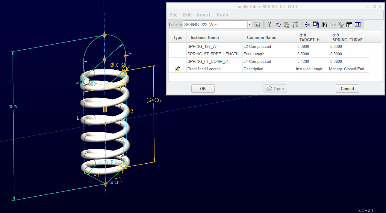
I created a single spring that covers the 3 lengths I need.
This is certainly not optimal when the spring is a generic part that should fit into a lot of product families where each length is just a tad different than the next design. Also notice I am managing the spring to a very specific application managing tangency to a sphere and a drill-point.
And yes, I put in a few part level relations for some simple calculations (OD, Wraps & Wire Dia). It is not meant to be a generic spring, but the family tables is meant to manage different stated throughout the assembly levels and drawing requirements. In this case, 3 for a single design. 1) free-length for explode state (and specification drawing). 2) Level 1 installed length when captivated in a cavity. 3) Actuated detent.
Yes there are flexible parts, but how do those behave in exploded assemblies? But you will also notice in the second dimension column that I am managing the closed end requirement. Stay tuned.
Downside so far is a slew of new files appearing in the work folder and being prompted every time I open the part as to what version I want to see. I'm sure I'll get over these, but I'll need to write a DOS batch file to clean up the folder if I make a habit of using FT's.
In a past life, when there was a need for alternate versions of a part, we used a technique for file naming:
The generic would remain the 1234567.prt, but when we needed a special configuration of the part, it would be names 1234567-7654321.prt where ...7654321 would be the assembly that the alternate fixed configuration was used in. I could see this working for naming the family table instance as well. But if you have a locked database of parts, somehow you need to get access the the file to create the new iteration where a new part in this technique can be checked in on the fly.
I hope someone at PTC is following this discussion as well. I am still wondering if there is a simple way to do what I am trying to achieve... or is this the depth that people typically start fudging their assemblies, master models and drawings.
Next I have to get the level 1 assembly to understand what spring is used under what condition. I already have a test assembly with all 3 states. I have already learned one of the pitfalls... turning on and off parts in family tables is -highly- dependent on what parts the switched parts are associated with in assembly relations.
The spring file attached is Creo 2.0 Parametric full version.
Jul 30, 2013
03:09 PM
- Mark as New
- Bookmark
- Subscribe
- Mute
- Subscribe to RSS Feed
- Permalink
- Notify Moderator
Please log in to access translation
Jul 30, 2013
03:09 PM
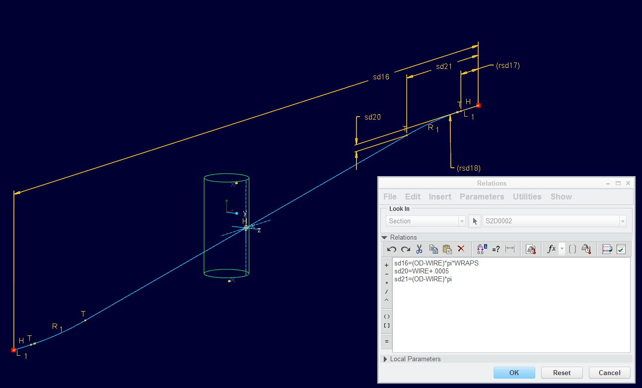
I got the closed end managed by relations in the Wrap sketch. Now I only have the one variable... or possible flexible component value to manage. Much better!
To explain the sketch: WRAPS is the number of turns of the spring (6.5 in this case), WIRE is wire diameter (.016"), OD is the actual spring OD (.122", not the wrap cylinder which is OD-WIRE).
The straight end and the curve down is intended to be the closed-end of the spring. By making the offset at 1 full turn (sd21) and just a smidgens over the wire diameter down (sd20), I will always have a slight gap at the closed end. This method also removed the ambiguity of the small straight length remaining at the ends (rsd17). Note the radius and the straight length are now reference.
Jul 30, 2013
03:26 PM
- Mark as New
- Bookmark
- Subscribe
- Mute
- Subscribe to RSS Feed
- Permalink
- Notify Moderator
Please log in to access translation
Jul 30, 2013
03:26 PM
Hmmmmm, looks familiar......  Nice! sorry I haven't had much time to look at the file, I'm getting ready for my trip!
Jul 30, 2013
03:29 PM
- Mark as New
- Bookmark
- Subscribe
- Mute
- Subscribe to RSS Feed
- Permalink
- Notify Moderator
Please log in to access translation
Jul 30, 2013
03:29 PM
Have a safe trip Frank!
(and no, I haven't peeked at your file )
Jul 29, 2013
11:42 AM
- Mark as New
- Bookmark
- Subscribe
- Mute
- Subscribe to RSS Feed
- Permalink
- Notify Moderator
Please log in to access translation
Jul 29, 2013
11:42 AM
To add to some confusion and complexity for you, you can looks at using the look up instance function if your assembly model had parameters that would drive the spring height.
If you search help center for "lookup instance" you should find this. If you want more specifics I would be more than willing to help.
To Replace Family Table–Driven Components
You can automatically replace family table–driven components according to design criteria by using the lookup_inst function. With this function, you can search a component family table to find an instance that fits the values of the search parameters. If the lookup function does not find a match, it returns the name of the generic.
The format for lookup_inst is:
lookup_inst ("generic_name", match_mode, “param_name_1”, match_value_1, “param_name_2”, match_value_2,...)
where
- generic name—Name of the generic model with a prt or asm extension
- match_mode—One of the following values:
- –1 (find closest instance with param values less than or equal to supplied values)
- 0 (find instance with param values that match supplied values exactly)
- 1 (find closest instance with param values greater than or equal to supplied values)
- param_name_1—Family table parameter name
- match_value_1—Value to match against
Here is the example.
Example: Replacing Family Table-Driven Components
Given an assembly that consists of a block and a peg, assemble the instance that matches the diameter of the hole in the block.
inst_name = declared string parameter initialized to generic part name
generic_name = peg.prt. This part contains a number of instances based on diameter dimension (d) and length dimension (d1).
Family instance names of peg.prt include:
2 x 4 - d0 = 2, d1 = 4
2 x 5 - d0 = 2, d1 = 5
2 x 6 - d0 = 2, d1 = 6
3 x 4 - d0 = 3, d1 = 4
3 x 5 ............
3 x 6 ............
Add a relation to the control in which peg.prt is added to an assembly controlled by dimensions of a feature in block.prt. The relation is:
inst_name = lookup_inst ("peg.prt", 0 , "d2", d6:0, "d1", d5:0 +1)
In this way, the instance of peg.prt being assembled to blockpeg.asm is controlled, based on the dimensions of the hole in block.prt.
The Pro/PROGRAM listing would look like this:
INPUT
END INPUT
RELATIONS
INST_NAME = LOOKUP_INST ("PEG.PRT", 0, "D2", D6:0, "D1", D5:0 + 1)
END RELATIONS
ADD PART BLOCK
INTERNAL COMPONENT ID 1
END ADD
ADD PART (INST_NAME)
INTERNAL COMPONENT ID 2
PARENTS = 1 (#1)
END ADD
MASSPROP
END MASSPROP
Jul 29, 2013
12:01 PM
- Mark as New
- Bookmark
- Subscribe
- Mute
- Subscribe to RSS Feed
- Permalink
- Notify Moderator
Please log in to access translation
Jul 29, 2013
12:01 PM
Hey Andrew, that is excellent It may not be relevant in my quest but I do understand how this can be useful.
Jul 29, 2013
06:33 PM
- Mark as New
- Bookmark
- Subscribe
- Mute
- Subscribe to RSS Feed
- Permalink
- Notify Moderator
Please log in to access translation
Jul 29, 2013
06:33 PM
Just adding this in late, but how about using Interchange Assembly and Pro/Program?
Jul 29, 2013
06:41 PM
- Mark as New
- Bookmark
- Subscribe
- Mute
- Subscribe to RSS Feed
- Permalink
- Notify Moderator
Please log in to access translation
Jul 29, 2013
06:41 PM
There is no such thing as late in this discussion. It is an exploratory discussion to ferret out the best way to achieve a real world operation.
I have never used Pro|Program and I know nothing about Interchange Assembly. Please expand on your thought.
Jul 30, 2013
08:33 AM
- Mark as New
- Bookmark
- Subscribe
- Mute
- Subscribe to RSS Feed
- Permalink
- Notify Moderator
Please log in to access translation
Jul 30, 2013
08:33 AM
Tom,
I think you really should use flexible parts for springs.
You only have one spring (can even be a family table part) and tie one driving dimension to a distance in the assembly to achieve different lengths. I think Creo solves this by switching the spring to an internal family table spring transparent to the user.
If the distance in the assembly changes, the spring will adapt. In mechanism you have to regenerate.
In short, one model per spring, compressed length through flexible parts. No need to clutter your database with springs of compressed length.
In really large assemblies performance may suffer.
Reinhard
edit
The same applies to O-rings where I make inner diameter and cord diameter flexible. I do not model the deflection of the ring.
- Flexible components cannot change length from one view to another; not much help.
please elaborate
- The assembly model exploded view -should- swap out the sprung springs with unsprung springs when viewing the exploded view. This is a candidate for view states.
dont know about that
- Also, detent springs actually have 3 states; unsprung (for part drawings), installed (for subassembly drawings), and actuated (for top level drawing).
--unsprung (for part drawings) will be shown as modelled
--installed (for subassembly drawings) will be shown as built in
--actuated (for top level drawing) will be shown as built in
Jul 30, 2013
11:54 AM
- Mark as New
- Bookmark
- Subscribe
- Mute
- Subscribe to RSS Feed
- Permalink
- Notify Moderator
Please log in to access translation
Jul 30, 2013
11:54 AM
True, I can use this method until I get to the exploded view state. And yes, Flexible components are a family table function. I do have to manage 2 parameters per spring as I also desire to manage the closed end of the spring which changes from one length to the next. I might be able to solve that though.
I am also not to sure if a flexible component will flex through 2 levels. I will have to try that. Say I have a drawing open with the subassembly in the drawing and the spring is at the compressed state where the ball is tangent to a keeper. And I also have the next level open where the ball is detente to the flush surface and that drawing is open. Do you think both would be shown properly? This I will have to try.
The explode state, with free-length springs would follow my fallback version where the springs are added to a next level assembly and added to the drawing separately. In fact, this is really a very simple method to sustain. Even here I can use family tables from a single spring.
I to have done many o-rings assemblies for vacuum designs. In some cases, even showing them squished. as installed.
I've attached the visual of the test case. Right now it is a huge mess. It has 2 balls installed and 3 versions of the family table spring. This assembly also has a family table to allow representation of each state.
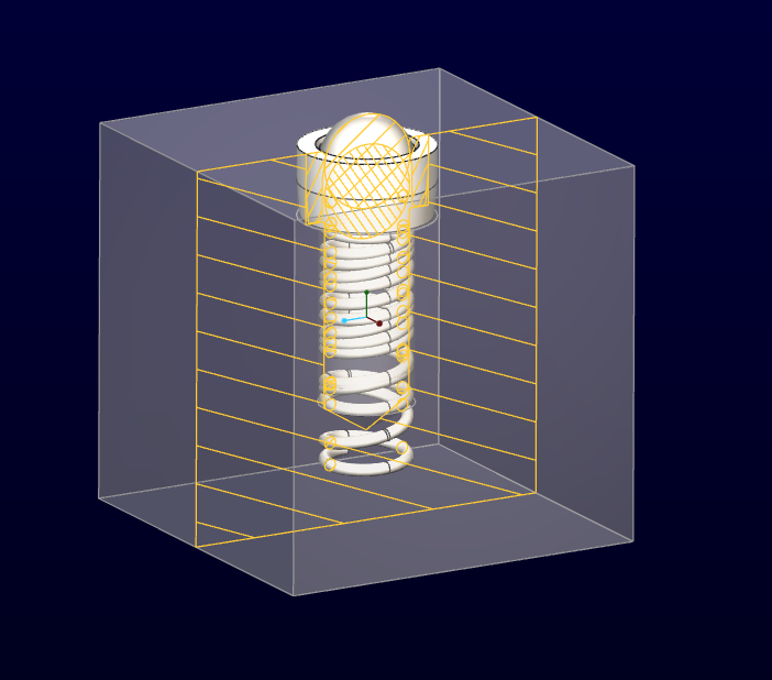
Multiply this by 7!
Jul 30, 2013
01:01 PM
- Mark as New
- Bookmark
- Subscribe
- Mute
- Subscribe to RSS Feed
- Permalink
- Notify Moderator
Please log in to access translation
Jul 30, 2013
01:01 PM
Hello Tom
>>I am also not to sure if a flexible component will flex through 2 levels. I will have to try that. Say I have a drawing open with the subassembly in the drawing and the spring is at the compressed state where the ball is tangent to a keeper. And I also have the next level open where the ball is detente to the flush surface and that drawing is open. Do you think both would be shown properly? This I will have to try.<<
dont think so. The subassembly in session only exists once regardless where it is used and it will have the same session ID. I use mechanism and snapshots for different positions in drawing.
>>I've attached the visual of the test case. Right now it is a huge mess. It has 2 balls installed and 3 versions of the family table spring. This assembly also has a family table to allow representation of each state.<<
You could create a datum plane at the ball where the spring touches. (inner diameter of the spring). Assemble the spring to bottom and axis of the hole, make the spring flexible from bottom to datum plane. Then you can move the ball arrond and the spring will follow.
You can use mechanism for the position of the ball but you have to regenrate for the spring to adapt.
Regards
Reinhard
Jul 30, 2013
01:42 PM
- Mark as New
- Bookmark
- Subscribe
- Mute
- Subscribe to RSS Feed
- Permalink
- Notify Moderator
Please log in to access translation
Jul 30, 2013
01:42 PM
So here is the real world scenario for a lot of these "best practice" discussions. Yes, we can get fancy and to employ mechanism is an interesting idea but is it necessary? Obviously it shouldn't be. In this case, you can easily see that someone will want to open all the drawings and print them. They will not remember to regenerate or have them look to see if the drawing is the same as when it was saved. All they care about is getting the job done... job being, "...please print me a document package". I, as an engineer, have to know it will print exactly as I intended. Even with the simple method I came up with, I had to double check every level because the explode on one level seems to affect the explode on the next. This is scary!
I know we are just thinking here. I have a great deal of experience when it comes to sustainability of data sets. In the life of a CAD model and drawing sets, you might have a dozen different "drafters" and "designers" tweaking your model over a decade. Some are minimum wage or even off-site contract services and others are junior engineers that take your original model and make the next generation (which soon becomes the current production model). I can promise you, they will -never- follow through on a complex modeling scheme.
Yes, I can manage a flexible model in several ways, that is no issue. Again, I will test what you are saying in my application, but if cannot open 2 drawings simultaneously and have them open with the correct representation, then this is not an acceptable method for a typical production environment where drawings and models are handed over to a sustaining engineering group.
To follow up, you can see how the flexible model in this application is not only the spring, but also the ball. It too changes position from one level to the next. I can see being able to do this without too much trouble with assembly family tables where you have one version in the drawing and another model in the next level assembly. I can make the spring dimension variable in the family table.
I know this is a simple case, but the application is universal.
Jul 30, 2013
02:20 PM
- Mark as New
- Bookmark
- Subscribe
- Mute
- Subscribe to RSS Feed
- Permalink
- Notify Moderator
Please log in to access translation
Jul 30, 2013
02:20 PM
Tom,
the beauty of flexible components and mechanism is you only have one model. Users of a PLM system will appreciate it as no unnecessary objects have to be handled.
In drawing you can attach a snapshot to a view so multiple assemblies of the same group for position are not necessary.
In your model the ball is positioned in mechanism, the spring is flexible which has nothing to do with mechanism.
Reinhard
Jul 30, 2013
02:43 PM
- Mark as New
- Bookmark
- Subscribe
- Mute
- Subscribe to RSS Feed
- Permalink
- Notify Moderator
Please log in to access translation
Jul 30, 2013
02:43 PM
I will have to look into snapshots for views more. This could have strong implications in view management.
Am I correct in assuming by mechanism you simply mean mechanism assembly contraints? This is much simpler to manage than than a full blown mechanism analysis.
I may be able to manage exploded views (free length springs) with careful management of the constraints where the ball can actually be separated from the spring in a valid assembly constraint.
Anyone know if you can put upper and lower limits on a flexible component (dimension limits) in the table?
Certainly worth exploring the possibilities.
Last question for this post: Where or how do you specify a Snapshot as a drawing view? It is not an option in the view properties dialog that I can see.
Jul 30, 2013
04:15 PM
- Mark as New
- Bookmark
- Subscribe
- Mute
- Subscribe to RSS Feed
- Permalink
- Notify Moderator
Please log in to access translation
Jul 30, 2013
04:15 PM
Hello Tom,
- I use mechanism kinematic (formerly MDX) which is part of the foundation packet.
- You can write a relation like
if d23 > 60
d23=60
endif
if d23< 40
d23=40
endif
but I havent tried it with flexible components
You can set upper and lower limits for components in mechanism
- Attaching a snapshot to a view should be under
#properties
#view states
#explode components in view checked
in the assembly explode state pulldown menue you should find the snapshot (if it exists)
Have fun with mechanism
Reinhard
edit
Just to make sure there is no misunderstanding, I use flexible components, not flexible modelling which was introduced in Creo.
Jul 31, 2013
01:37 AM
- Mark as New
- Bookmark
- Subscribe
- Mute
- Subscribe to RSS Feed
- Permalink
- Notify Moderator
Please log in to access translation
Jul 31, 2013
01:37 AM
I spent a good evening working with flexible models. Somewhat limited but I think I can get there between this and family tables. I was able to make the variation between 2 assembly levels where the spring started out at the free length, but I was getting a lot of warning prompts. The good news is that I could switch from one model to the other and they were properly displayed. I could even mix the two in the top level assembly. It was the explode state that I needed to make in a family table. Next I need to add the drawings and see how they behave once I get rid of the warning prompts.
So this is where I got:
Spring part: no family tables; modeled at free length; variable with 1 strong dimension (not a relation or parameter). Tested to obtain nearly a full range of the spring's capabilities.
Level 1 assembly: Flexible model (spring); type dimension value; locked value (derived from measuring); ball follows spring - learned that a tangent spring wire to a drill point angled face are highly unreliable and flips on a whim!
Created an Explode state family table with the same dimension so I can use the generic and the FT instance in a drawing to show the section view and the exploded view, both correctly.
Level 2 assembly; added 2 level 1 assemblies and made each L1 assembly flexible and was thereby able to change the dimension in the spring yet again. Use a different value in each sub-components. The level 1 assembly was not affected.
Errors kept me from going any further at this point. I don't know if I ran into a limitation, if this is normal, or if this really is an issue to avoid in models.
Jul 31, 2013
05:39 AM
- Mark as New
- Bookmark
- Subscribe
- Mute
- Subscribe to RSS Feed
- Permalink
- Notify Moderator
Please log in to access translation
Jul 31, 2013
05:39 AM
Hello Tom,
I did some testing in a spring-ball assembly. Ball in mechanism, spring flexible.
- ball can be moved, upper and lower limits can be set
- exiting mechanism and regenerating makes the spring adapt.
- snapshots work in modelling, regenerating makes the spring adapt
- upper and lower limits for spring length can be set by relations
- snapshots can be assigned to views, position of components according to snapshot ok
- flexible component (spring) is tied to model, will not adapt to snapshot
So I am sorry to say that snapshots and flexible components do not work in drawings
Reinhard
PS
I try to avoid solo tangent constraints as they have two solutions (they flip)
Jul 31, 2013
05:30 PM
- Mark as New
- Bookmark
- Subscribe
- Mute
- Subscribe to RSS Feed
- Permalink
- Notify Moderator
Please log in to access translation
Jul 31, 2013
05:30 PM
Thank you for doing that, Reinhard. Glad to learn about snapshots for views. Will definitely explore this further.
Aug 01, 2013
04:04 AM
- Mark as New
- Bookmark
- Subscribe
- Mute
- Subscribe to RSS Feed
- Permalink
- Notify Moderator
Please log in to access translation
Aug 01, 2013
04:04 AM
This is my impression how Creo works:
- Creo creates a family table in each flexible component with one instance for each position
- Creo creates a family table in the assembly that states which component will be switched to which component family table instance
All this is done internally, transparent to the user.
- Mechanism only moves components arround, snapshots are sets of component positions
Flexible components are tied to the assembly, not to the snapshot. Therefore flexible components in drawing views will not adapt according to snapshot.
Reinhard
Aug 01, 2013
09:56 AM
- Mark as New
- Bookmark
- Subscribe
- Mute
- Subscribe to RSS Feed
- Permalink
- Notify Moderator
Please log in to access translation
Aug 01, 2013
09:56 AM
Ok, haven't played with the snapshot thing, but I'm sure you can make instances of the lwer level assembly with the "flexible" springs at different stages of compression (from free length to coil bind), then use those instances in an instance of an upper level assembly family table, getting you what I think Antonious is looking for.
When I get time today I'm going to try that out. I made a compression spring that has built in flexibility and it worked great in the mechanisms I used it in.
Aug 01, 2013
01:18 PM
- Mark as New
- Bookmark
- Subscribe
- Mute
- Subscribe to RSS Feed
- Permalink
- Notify Moderator
Please log in to access translation
Aug 01, 2013
01:18 PM
Reinhard, I I have a real world application now for this exact requirement so I have some time to experiment. What you say is very apparant. If I want the varying stages of a mechanism to show on a single drawing, I need family tables in the model.
I tried to change the spring in the assembly with family tables. I ended up having to drive it with a flexible component in the assembly tree. It would not let me change the spring length because it was driven by a relation. I removed the relation so it could be driven by the parameter "length" instead. I could not find a way to tie the parameter "new value" with an assembly feature... I could not drive the flexible component with a "dimension" because it was parameter driven. I wanted to use a length measurement to drive it, but you can only do this in dimension driven flexible fields and parameter driven fields (that I could tell).
Then I try to drive the new flexible parameter "length" in the spring with the assembly's family table and for some reason, I could not get to that field any way I tried. So now I have a 3-stage family table (+ generic) to drive my model assembly (single level). I have 2 flexible components... (4 actually) I had to assembly 2 springs, each flexible, but with different values. I have 2 o-rings installed; one in free state and one in compressed state (2 version modeled at the part level). Now my master model is a mess because it has extra part. I don't like it, but it what it is with my current level of understanding.
Now my drawing management is simple. I install the model instances I want in the drawing and I can create views accordingly in all 3 special conditions. The flexible components let me fix the spring length for each state. The o-ring is driven by a family table in the o-ring file. One of each instance of the o-ring is installed in the assembly, and 2 master springs are installed in the assembly, again, each driven by a flexible component parameter value.
Furthermore, I did find the assembly constraint parameters in the family table columns. I have 3 that drive general degrees of freedom for 3 components. Each constraint has limits and no regen values.
In the assembly's family table I now have all the elements I need to control the 3 states:
Mechanism Constraints
- Rod position (rotation for a curved spring)
- Actuator position
- Source position
Display State
- O-ring free on/off
- O-ring squished on/off
- short spring on/off
- long spring on/off
Family table parts installed
- 2 O-rings
Flexible components
- 2 Springs (2 states of the same part)
Drawings
- 3 separate instances of the assembly model using the same section in 3 views.
This is how far this discussion has brought me to date (very timely as well I might add).
Here is what still bugs me... I have the duplicated parts assembled in my assembly. I cannot seem to drive the flexible components with the assembly's family table; I cannot drive a parameter driven variable in flexible components with an assembly feature (simply can't select at the sub-component's dimension). I cannot seem to switch instances of sub-components with family tables, but only toggle a component on/off. if I could toggle them, it would solve the duplication issue for component level instances.
Here is what -is- working for me; driving the assembly constraints from the family tables is nice although a little awkward. I also like that family table instances share a bulk of the work managed by the display manager such as sections.
I haven't needed display states as yet. I will when I prepare my presentation slides. The goal is a static, but reproducible presentation with specific comparable model views and a dimensioned reference drawing covering the various states.


