
Turn on suggestions
Auto-suggest helps you quickly narrow down your search results by suggesting possible matches as you type.
Showing results for
Please log in to access translation
Turn on suggestions
Auto-suggest helps you quickly narrow down your search results by suggesting possible matches as you type.
Showing results for
Community Tip - When posting, your subject should be specific and summarize your question. Here are some additional tips on asking a great question. X
- Community
- Creo+ and Creo Parametric
- 3D Part & Assembly Design
- Re: How do you populate a table with a pattern tab...
Translate the entire conversation x
Please log in to access translation
Options
- Subscribe to RSS Feed
- Mark Topic as New
- Mark Topic as Read
- Float this Topic for Current User
- Bookmark
- Subscribe
- Mute
- Printer Friendly Page
How do you populate a table with a pattern table feature
Oct 10, 2023
12:11 PM
- Mark as New
- Bookmark
- Subscribe
- Mute
- Subscribe to RSS Feed
- Permalink
- Notify Moderator
Please log in to access translation
Oct 10, 2023
12:11 PM
How do you populate a table with a pattern table feature
How can I populate table using dimensions from a pattern table? All Csys are in a pattern table. I am using Creo 7.0.5.0
__PRESENT
__PRESENT
__PRESENT
Solved! Go to Solution.
ACCEPTED SOLUTION
Accepted Solutions
Oct 10, 2023
06:35 PM
- Mark as New
- Bookmark
- Subscribe
- Mute
- Subscribe to RSS Feed
- Permalink
- Notify Moderator
Please log in to access translation
Oct 10, 2023
06:35 PM
Enclosed is a Creo 7 part and drawing for reference. This is not the only way to do this, but it is the most robust IMO for most scenarios. There is a pattern of csys features in the model. Note that I have created a measure analysis feature to get the offset values relative to the reference csys you want to measure from, this will account for the negative values if there are any and avoid the "incorrectly" signed (+/-) values associated with pattern parameter values. I only filled the table for the first 3 csys features.

Note the table display:

Syntax required to use the measure value parameter from the analysis feature FID_XXX is the feature ID and is unique:

========================================
Involute Development, LLC
Consulting Engineers
Specialists in Creo Parametric
Involute Development, LLC
Consulting Engineers
Specialists in Creo Parametric
10 REPLIES 10
Oct 10, 2023
01:23 PM
- Mark as New
- Bookmark
- Subscribe
- Mute
- Subscribe to RSS Feed
- Permalink
- Notify Moderator
Please log in to access translation
Oct 10, 2023
01:23 PM
I assume you are wanting to populate a drawing table, but this is not explicitly stated in your post. All dimensions from the pattern table are available for use via relations or parameter names of the dimensions.
In drawing mode Creo will only display a single instance of a dimension within the drawing, so it may not be possible to show the dimension in a view and in a table in the drawing simultaneously. If that is your problem, create a parameter for each table entry and assign the dimension value to the parameter, then you can use it (parameter name) in a table.
If this is not the issue, then elaborate on what hurdle you are facing.
========================================
Involute Development, LLC
Consulting Engineers
Specialists in Creo Parametric
Involute Development, LLC
Consulting Engineers
Specialists in Creo Parametric
Oct 10, 2023
02:46 PM
- Mark as New
- Bookmark
- Subscribe
- Mute
- Subscribe to RSS Feed
- Permalink
- Notify Moderator
Please log in to access translation
Oct 10, 2023
02:46 PM
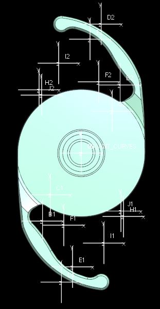
I would like to create a table on a dwg that will populate with the dimensions of the coordinates show in the attached image. All the coordinates are center points for arcs that define a curve used as a profile for the part.

__PRESENT
__PRESENT
__PRESENT
__PRESENT
__PRESENT
__PRESENT
Oct 10, 2023
03:11 PM
- Mark as New
- Bookmark
- Subscribe
- Mute
- Subscribe to RSS Feed
- Permalink
- Notify Moderator
Please log in to access translation
Oct 10, 2023
03:11 PM
I am still making assumptions based on your description as the problem statement is incomplete. You are leaving out most of the information needed to definitively generate a viable solution. Post the model to avoid having to write a treatise on what the constraints are. If you are not able to post the model, then you need to be more specific about the data structures involved.
How were the csys shown in your picture created? Are they all datum csys features? Were they created in sketch or part mode?
========================================
Involute Development, LLC
Consulting Engineers
Specialists in Creo Parametric
Involute Development, LLC
Consulting Engineers
Specialists in Creo Parametric
Oct 10, 2023
05:02 PM
- Mark as New
- Bookmark
- Subscribe
- Mute
- Subscribe to RSS Feed
- Permalink
- Notify Moderator
Please log in to access translation
Oct 10, 2023
05:02 PM
The csys were created in part mode. The first csys was created offset from an existing csys. That csys was patterned giving csys A-J. It is the csys label and x, y dims I would like to add to a table on the dwg to depict the center of the arcs of the inside blue profile. This model is the generic of a family table. The profile will not change on any of the instances. Other features change not affecting the profile. Sorry if I am making this more complicated than it should be.


In the current dwg, an attempt was made to show a table with these dims. As you can see, the dims are incorrect. 2x R30.00, per the table, has 2 arcs at the same location which is not true. They both lie on Y 0 but X is -27.00 and 27.00. The same is true for other arc centers. I would like to generate a table showing true values.
Oct 10, 2023
05:07 PM
- Mark as New
- Bookmark
- Subscribe
- Mute
- Subscribe to RSS Feed
- Permalink
- Notify Moderator
Please log in to access translation
Oct 10, 2023
05:07 PM
Sorry, Forgot to add dwg.

Oct 10, 2023
06:35 PM
- Mark as New
- Bookmark
- Subscribe
- Mute
- Subscribe to RSS Feed
- Permalink
- Notify Moderator
Please log in to access translation
Oct 10, 2023
06:35 PM
Enclosed is a Creo 7 part and drawing for reference. This is not the only way to do this, but it is the most robust IMO for most scenarios. There is a pattern of csys features in the model. Note that I have created a measure analysis feature to get the offset values relative to the reference csys you want to measure from, this will account for the negative values if there are any and avoid the "incorrectly" signed (+/-) values associated with pattern parameter values. I only filled the table for the first 3 csys features.
Note the table display:
Syntax required to use the measure value parameter from the analysis feature FID_XXX is the feature ID and is unique:
========================================
Involute Development, LLC
Consulting Engineers
Specialists in Creo Parametric
Involute Development, LLC
Consulting Engineers
Specialists in Creo Parametric
Oct 11, 2023
10:47 AM
- Mark as New
- Bookmark
- Subscribe
- Mute
- Subscribe to RSS Feed
- Permalink
- Notify Moderator
Please log in to access translation
Oct 11, 2023
10:47 AM
This will work. Thank you.
Oct 11, 2023
10:55 AM
- Mark as New
- Bookmark
- Subscribe
- Mute
- Subscribe to RSS Feed
- Permalink
- Notify Moderator
Please log in to access translation
Oct 11, 2023
10:55 AM
Good to know it is working for you. For future reference of others, would you please change the marked solution to the post where the models and explanations were included. The currently marked solution is your response stating it works.
========================================
Involute Development, LLC
Consulting Engineers
Specialists in Creo Parametric
Involute Development, LLC
Consulting Engineers
Specialists in Creo Parametric
Oct 16, 2023
03:58 AM
- Mark as New
- Bookmark
- Subscribe
- Mute
- Subscribe to RSS Feed
- Permalink
- Notify Moderator
Please log in to access translation
Oct 16, 2023
03:58 AM
I think there's a much easier solution. Add a point to one of the coordinate systems and make a reference pattern. Then add a Hole Table on the drawing. This will list the coordinates of all the points, no manual work needed. See attached Creo 7 file.

EDIT: Note that you can edit the hole chart, and you don't need to list the Z dimension:

Oct 16, 2023
10:06 AM
- Mark as New
- Bookmark
- Subscribe
- Mute
- Subscribe to RSS Feed
- Permalink
- Notify Moderator
Please log in to access translation
Oct 16, 2023
10:06 AM
There are known issues with hole tables updating accurately when modifying models so test this approach for your particular application before relying on it. Hole tables do not update automatically with model/dwg regeneration in Creo. The user must manually use the update tables function in drawing mode to update the table.
========================================
Involute Development, LLC
Consulting Engineers
Specialists in Creo Parametric
Involute Development, LLC
Consulting Engineers
Specialists in Creo Parametric


