Turn on suggestions
Auto-suggest helps you quickly narrow down your search results by suggesting possible matches as you type.
Showing results for
Please log in to access translation
Turn on suggestions
Auto-suggest helps you quickly narrow down your search results by suggesting possible matches as you type.
Showing results for
Community Tip - You can subscribe to a forum, label or individual post and receive email notifications when someone posts a new topic or reply. Learn more! X
- Community
- Creo+ and Creo Parametric
- 3D Part & Assembly Design
- Re: How do you set correct view naming?
Translate the entire conversation x
Please log in to access translation
Options
- Subscribe to RSS Feed
- Mark Topic as New
- Mark Topic as Read
- Float this Topic for Current User
- Bookmark
- Subscribe
- Mute
- Printer Friendly Page
How do you set correct view naming?
Jul 09, 2012
05:13 PM
- Mark as New
- Bookmark
- Subscribe
- Mute
- Subscribe to RSS Feed
- Permalink
- Notify Moderator
Please log in to access translation
Jul 09, 2012
05:13 PM
How do you set correct view naming?
I imported an IGES framework of sketches from our other CAD system so I could have a skeleton for building this model from scratch in Creo.
As I was working through the model it was apparent that I made an orientation placement error as the named views did not match up with the part orientation I was building.
When I completed the model I discovered that my model was in the intended XYZ orientation, only the view naming did not make sense.
I am not sure why what I would consider the Top actually is the Front view. When I think of the top of anything I would automatically assume I was looking down at it from the Z direction.
I imagine the way this is set up in Creo makes sense to some type of product developement, but it is very misleading to us.
How can I permanently set my orientation up to have Z direction refer to top and bottom views, and front to a 90 degree rotation from this?
Thank you,
Paul
This thread is inactive and closed by the PTC Community Management Team. If you would like to provide a reply and re-open this thread, please notify the moderator and reference the thread. You may also use "Start a topic" button to ask a new question. Please be sure to include what version of the PTC product you are using so another community member knowledgeable about your version may be able to assist.
Labels:
- Labels:
-
2D Drawing
13 REPLIES 13
Jul 11, 2012
06:55 AM
- Mark as New
- Bookmark
- Subscribe
- Mute
- Subscribe to RSS Feed
- Permalink
- Notify Moderator
Please log in to access translation
Jul 11, 2012
06:55 AM
I think I stumbled onto part of my own answer. I renamed my views in the feature tree in the template file. Now when I bring up a new model the datum planes are named what appears to be their natural orientation.
Unfortunately; the named views do not match up to the renamed datums. This has me thinking that there must be a better way of having the datum planes named appropriately.
Jul 11, 2012
01:30 PM
- Mark as New
- Bookmark
- Subscribe
- Mute
- Subscribe to RSS Feed
- Permalink
- Notify Moderator
Please log in to access translation
Jul 11, 2012
01:30 PM
I now have changed the datum names as well as the view names to my liking. I just don't like the long and tedius process involved to get the model facing in conjunction with recognizable views. The CAD package we are replacing has the view orientation lined up with XYZ in a very logical sense. I would like to think that Creo would at least have a way of choosing between view orientation methods.
Is there no config file that gives you the alternate view orientations?
Just in case someone else needs to know how this can be changed this is what I did.
1) Open default template model
2) Change default datum names in feature tree
3) Go to desired view
4) Under the named views icon hit the reorient function
5) You then can either rename each view or dynamically modify each view orientation
Jul 11, 2012
02:43 PM
- Mark as New
- Bookmark
- Subscribe
- Mute
- Subscribe to RSS Feed
- Permalink
- Notify Moderator
Please log in to access translation
Jul 11, 2012
02:43 PM
Its not easy but you can create mapkeys for automatic creation of starting datums and default views based on CSYS as first feature and its axes orientation.
It gets pretty usefull if you've got part in your assembly placed under some strange angle or two angles and its origin is somewhere far away.
Jul 11, 2012
03:18 PM
- Mark as New
- Bookmark
- Subscribe
- Mute
- Subscribe to RSS Feed
- Permalink
- Notify Moderator
Please log in to access translation
Jul 11, 2012
03:18 PM
I've heard of the concept of mapkeys but haven't learned anything about it. This could be a useful tool for something like this.
The method I used was quite a tedious process.
I'm thinking that if someone were to create a model from scratch without the default datums that you might be able to have more orientation flexibility. The mapkeys could be a shortcut to starting up models. I would like to figure out how this would work for an example like this.
Jul 11, 2012
03:50 PM
- Mark as New
- Bookmark
- Subscribe
- Mute
- Subscribe to RSS Feed
- Permalink
- Notify Moderator
Please log in to access translation
Jul 11, 2012
03:50 PM
An easier way would be to import the IGES into your company start part - that way you have the intended datum already there.
Insert->Shared Data->From File once you have opened your start part template.
Jul 11, 2012
04:50 PM
- Mark as New
- Bookmark
- Subscribe
- Mute
- Subscribe to RSS Feed
- Permalink
- Notify Moderator
Please log in to access translation
Jul 11, 2012
04:50 PM
The trouble I am having is with the default naming of Datum Planes and views. This doesn't match the XYZ environment that we thought was pretty much standard.
I would like to see a config option that would allow the different orientation setup.
Jul 13, 2012
02:53 PM
- Mark as New
- Bookmark
- Subscribe
- Mute
- Subscribe to RSS Feed
- Permalink
- Notify Moderator
Please log in to access translation
Jul 13, 2012
02:53 PM
Create a template that has the views names as you'd like them to be, then always use that template to create your new parts or import parts into.
Jul 16, 2012
07:17 AM
- Mark as New
- Bookmark
- Subscribe
- Mute
- Subscribe to RSS Feed
- Permalink
- Notify Moderator
Please log in to access translation
Jul 16, 2012
07:17 AM
Yes; this is the route I have chosen.
Even though this sets up a new part nicely I've discovered that this isn't perfect.
For instance when I import a model that is set up correctly as an inheritance model into a correctly defined template I see the old coordinate system's datum names along with the new template datum naming. I'm not sure yet how this will work with drawings.
I have found out that Pro Engineer's coordinate system is referred as the "Right Handed Coordinate System". This has X and Z on the flat plane and Y perpendicular to this.
The coordinate system that I am used to has X and Y on the flat plane and Z perpendicular to this. In essence it is the same as what the CSYS feature is. It is the same also to what the Mold package appears to be set up to. It is the same as what our dies are laid out in our CNC machine. I'm not even sure the name of this coordinate system; it might be referred to as the World Coordinate System, some one can correct me if I'm wrong.
Jul 16, 2012
07:29 AM
- Mark as New
- Bookmark
- Subscribe
- Mute
- Subscribe to RSS Feed
- Permalink
- Notify Moderator
Please log in to access translation
Jul 16, 2012
07:29 AM
"Right-handed" just means that if X is to the right (e.g. on a piece of paper) and Y is up, then Z is towards you. If you hold your right hand so that your thumb and first two fingers are all at right-angles to each other, then the thumb is X, first finger Y and second finger Z - whichever way round you position your hand.
I'm not aware of any common use of a left-handed coordinate system - coordinate systems are always defined right-handed.
Which one of those directions you choose to define as "up" is purely a matter of convention, and may well vary between different fields.
Jul 20, 2012
07:19 PM
- Mark as New
- Bookmark
- Subscribe
- Mute
- Subscribe to RSS Feed
- Permalink
- Notify Moderator
Please log in to access translation
Jul 20, 2012
07:19 PM
Hi Dennis...
What do you mean by "the old coordinate system's datum names"?
Typically when you import a model from IGES or STEP, etc. the model comes in with it's own coordinate system (exported from whatever package made the IGES/STEP). Your template also has a coordinate system. So naturally you'll see both. If this is an eyesore, you can layer off one of the coordinate systems (whichever one you want).
In your template, you could also edit the X,Y, and Z coordinate system so that z points up. Some aniamtion packages use this coordinate system type. You can easily change which axis is Z but I'm not sure if this fixes your issue.
I sense I'm missing something or misinterpreting the problem. It should be pretty easy to resolve the kind of issue you're discussing. If I'm misunderstanding, please let me know. 
Thanks!
-Brian
Jul 26, 2012
08:47 AM
- Mark as New
- Bookmark
- Subscribe
- Mute
- Subscribe to RSS Feed
- Permalink
- Notify Moderator
Please log in to access translation
Jul 26, 2012
08:47 AM
Hi Brian,
I just got back from a short vacation so I it's been a while between replying back.
In answer to your above question; when I bring a model into a default template inherited from another model I not only have the datum placement the way it was changed, the inherited model brings in the datum naming that I had prior to making this change, even though the inherited model in it's original file has my renamed datum structure.
I have modified the model template so that Z does point up and all the datum names and (most of the) views are set up properly.
What I'd like to avoid is having to set this up again every time there is a new creo release. I would also like this to not bring in the different set of datum names.
We have found that the view naming from our previous CAD system to be extremely helpful, and would like to be able to have this set as a default.
I guess the only way we can find a easy resolution to this is if Creo would make either a config or standard option that could have all datum and view naming set to the World Coordinate System. (Which is the same as the CSYS).
I've submitted this as an idea request and am hoping that this idea will catch on.
Jul 27, 2012
06:36 PM
- Mark as New
- Bookmark
- Subscribe
- Mute
- Subscribe to RSS Feed
- Permalink
- Notify Moderator
Please log in to access translation
Jul 27, 2012
06:36 PM
Hi Dennis...
I'm soooo confused! Are you using true Inheritance Models in Wildfire/Creo... or are you using inheritance as a way to describe a model from an external source?
I think maybe I need a screen shot! If I can see what you're talking about, I might be able to suggest a permanent fix... or at the very least a mapkey or script that could make the effort of defining the view names and axis directions almost effortless.
Thanks!
-Brian
Jul 29, 2012
08:54 AM
- Mark as New
- Bookmark
- Subscribe
- Mute
- Subscribe to RSS Feed
- Permalink
- Notify Moderator
Please log in to access translation
Jul 29, 2012
08:54 AM
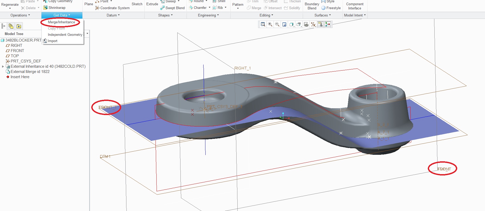
Hi Brian,
I've screen captured what I am referring to in regards to importing a different named set of datums. I've also shown how I imported the inheritance model.
The model that I imported has the datums named correctly in the part file I retrieved it from, yet it reverts back to Creo's default Right Hand Coordinate system when it is retrieved. That is shown where you see the circled areas that have double text.