
Turn on suggestions
Auto-suggest helps you quickly narrow down your search results by suggesting possible matches as you type.
Showing results for
Please log in to access translation
Turn on suggestions
Auto-suggest helps you quickly narrow down your search results by suggesting possible matches as you type.
Showing results for
Community Tip - Learn all about PTC Community Badges. Engage with PTC and see how many you can earn! X
- Community
- Creo+ and Creo Parametric
- 3D Part & Assembly Design
- How to apply a force/moment in Mechanica?
Translate the entire conversation x
Please log in to access translation
Options
- Subscribe to RSS Feed
- Mark Topic as New
- Mark Topic as Read
- Float this Topic for Current User
- Bookmark
- Subscribe
- Mute
- Printer Friendly Page
How to apply a force/moment in Mechanica?
Jun 30, 2011
10:57 AM
- Mark as New
- Bookmark
- Subscribe
- Mute
- Subscribe to RSS Feed
- Permalink
- Notify Moderator
Please log in to access translation
Jun 30, 2011
10:57 AM
How to apply a force/moment in Mechanica?
Good Day All,
Trying to apply a force & moment in mechanica to a surface on a part.
Do I have to apply this using Advance, Total Load, Uniform to get mechanica to apply the moment?
When I use a Simple Force/Moment Load mechanica ignors the Moment for some reason.
To close to the holiday and my brain needs a vacation.
Any help would be appreciated.
Thanks
Don Anderson
Labels:
- Labels:
-
Surfacing
16 REPLIES 16
Jun 30, 2011
11:02 AM
- Mark as New
- Bookmark
- Subscribe
- Mute
- Subscribe to RSS Feed
- Permalink
- Notify Moderator
Please log in to access translation
Jun 30, 2011
11:02 AM
Donald,
You must use TLAP (Total Load At Point) to apply moments to solid models. This is because rotation degrees of freedom do not exist in solid elements.
Randy Speed
President & CEO
Speed Consulting, LLC
(214) 213 4440
(214) 853-9221 fax
www.speedconsulting.com
You must use TLAP (Total Load At Point) to apply moments to solid models. This is because rotation degrees of freedom do not exist in solid elements.
Randy Speed
President & CEO
Speed Consulting, LLC
(214) 213 4440
(214) 853-9221 fax
www.speedconsulting.com
Jun 30, 2011
11:08 AM
- Mark as New
- Bookmark
- Subscribe
- Mute
- Subscribe to RSS Feed
- Permalink
- Notify Moderator
Please log in to access translation
Jun 30, 2011
11:08 AM
Hi Donald,
Total Load At Point will certainly work (I don't know about Total Load
Uniform).
3D FEA elements don't respond to moments applied to their nodes - the
nodes only have translation DOFs. By using TLAP, Mechanica translates
both explicit moments, and moments due to an offset application point,
into a force distribution.
Use the Preview button to see how the load will actually be applied.
HTH,
Jonathan
Jun 30, 2011
11:09 AM
- Mark as New
- Bookmark
- Subscribe
- Mute
- Subscribe to RSS Feed
- Permalink
- Notify Moderator
Please log in to access translation
Jun 30, 2011
11:09 AM
Don,
Don't forget that it is not possible to apply a moment to 3D solid
elements (I'm guessing the surface you wish to load is not a shell
element). Having said that, you can apply a "Total Load At Point"
(TLAP) and select the surface (3D elements) it would be spread upon.
This will apply loading to the surface that will represent the load and
moment that would exist. This technique is normally used for
transferring loads from MDO to Mechanica. You need to create a point
which represents the location the load is generated from (usually a
mechanism joint center). Provide the component loading and moments and
then select the surface. Mechanica will spread the force out over the
surface.
I hope this helps,
Chris
Christopher Kaswer
Principal Design Engineer
Covidien
Research and Development, Surgical Devices
60 Middletown Avenue
North Haven, CT 06473
(203) 492-7167 (office)
(203) 492-4011 (fax)
www.covidien.com
Jun 30, 2011
12:02 PM
- Mark as New
- Bookmark
- Subscribe
- Mute
- Subscribe to RSS Feed
- Permalink
- Notify Moderator
Please log in to access translation
Jun 30, 2011
12:02 PM
Don,
It is very difficult to control the local force distribution when using TLAPs to apply a moment to a 3D face.
I suggest paving the solid faces with shells of negligible stiffness. You can then apply the moment to the shell or underlying surface. You may want to exclude the load application region from stress convergence checking.
Good luck.
Joe Colich
Boeing - STL
Jun 30, 2011
01:15 PM
- Mark as New
- Bookmark
- Subscribe
- Mute
- Subscribe to RSS Feed
- Permalink
- Notify Moderator
Please log in to access translation
Jun 30, 2011
01:15 PM
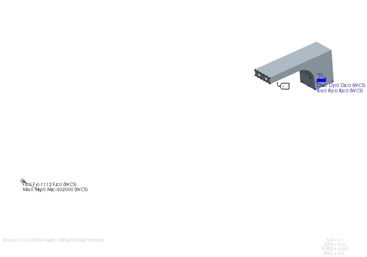
So say the end surface of the part sees a force that is applied by another part.That loadload onthe other part is applied 33"away from the mating face and the load applied is 250lb.
Would it be applied to the part as I have done in the attached image and part file, wildfire 4. This is just a quick model for discussion.
Thanks,
Don Anderson
Jun 30, 2011
02:26 PM
- Mark as New
- Bookmark
- Subscribe
- Mute
- Subscribe to RSS Feed
- Permalink
- Notify Moderator
Please log in to access translation
Jun 30, 2011
02:26 PM
Rotation degrees of freedomdo not exist in solid elements .
I'm usingTLAP with just the force going forward.
I will have to play with the shelled suface technique some more.
I was hoping not to have to add any additional features to the model for applying the load.
It appears that either way I have to add something and think it will be easier on others to figure out if I use TLAP
(Total Load at Point) This way I just have to add one datum point to the model.
The moment inthe load I was usingwas not needed as you pointed out and cancelling my foce I was applying. (thanks Chris)
Thanks again for the help and have a great Fourth of July Weekend.
Don Anderson
Jul 05, 2011
02:31 PM
- Mark as New
- Bookmark
- Subscribe
- Mute
- Subscribe to RSS Feed
- Permalink
- Notify Moderator
Please log in to access translation
Jul 05, 2011
02:31 PM
We ran into this force distribution issue last week, where the TLAP applies forces not normal to the surfaces. I could think of only one workaround, and that was to apply the force directly, normal to the surfaces, after a little statics hand calculations.We did not use the TLAP, we used force on surface. It actually worked out fairly easily for us.
Randy Speed
President & CEO
Speed Consulting, LLC
(214) 213 4440
(214) 853-9221 fax
www.speedconsulting.com
Randy Speed
President & CEO
Speed Consulting, LLC
(214) 213 4440
(214) 853-9221 fax
www.speedconsulting.com
Jul 05, 2011
02:50 PM
- Mark as New
- Bookmark
- Subscribe
- Mute
- Subscribe to RSS Feed
- Permalink
- Notify Moderator
Please log in to access translation
Jul 05, 2011
02:50 PM
Joe,
In your opinion do you believe this lack of control could stem from the mesh
distribution on the applied face?
Meaning, if the forces are applied at nodes and if a more uniform mesh
existed on the solid 3D face do you
believe that that would provide more control over the distribution?
I could envision a very coarse mesh on the end of a shaft let's say where a
moment being applied with TLAP
causing problems.
Curious what others think too.
Steve
Jul 05, 2011
06:14 PM
- Mark as New
- Bookmark
- Subscribe
- Mute
- Subscribe to RSS Feed
- Permalink
- Notify Moderator
Please log in to access translation
Jul 05, 2011
06:14 PM
Even though the load does end up on the elements, MECHANICA applies the TLAP load as a "distributed" load onto geometry, that is to the "surface", and not to the points or elements. So I would be surprised if the element mesh is related to TLAP load distribution.
Expanding on Joe's comment that "... it is difficult to control the local force distribution" using TLAP, I have found this to be true specifically when you are trying to represent two parts in contact where the issue of normal and tangential directions comes into play (direction really, not so much distribution). Theoretically (with no friction) the forces should be normal to the surface. This is not what we get. We get some normal forces along with some overlapping tangential forces.
The simplified example of the shaft end with applied moment coaxial to the axis of the cylindrical shaft (pure torsion) is a classic example of TLAP functionality. The forces are 100% applied tangentially to the plane of the cut shaft. This type of load application is correct when coming from a weld, or some other type of connection in real life where the part stiffness is continuous. However when the user desires to replace a part within the assembly (which would otherwise transfer forces to the meshed part via contact,) with a TLAP, normal forces are desired (not tangential forces).
In summary, my observation is that there seems to be no control as to normal/tangential portions of the applied force resulting from a TLAP. In the end however, the TLAP does indeed "balance" the applied forces - which is a good thing. For our contact substitution problem, we abandoned the TLAP and used old fashioned statics to apply the load normal to the surfaces to get around this issue and all was good. I suppose that tangential applied loads would be acceptable if the localized area of load application were far enough away from the area of interest, or if there were significant friction forces present.
Randy Speed
President & CEO
Speed Consulting, LLC
(214) 213 4440
(214) 853-9221 fax
www.speedconsulting.com
Jul 05, 2011
06:39 PM
- Mark as New
- Bookmark
- Subscribe
- Mute
- Subscribe to RSS Feed
- Permalink
- Notify Moderator
Please log in to access translation
Jul 05, 2011
06:39 PM
I guess I was envisioning the application as having the moment axis normal
to the surface (tangential).
I agree with you of using normal surface forces when applying a
torque/moment to the keyway of a
shaft where the applied surface is parallel to the moment axis or other
similar applications.
I guess I will have to wait for Joe's response, because I am a little
confused on the distribution issue.
While I agree with you that the load is distributed on the geometry, there
still has to be some level
of interpolation behind the scenes in order to apply equivalent point forces
at the nodes of the
elements. My thought train was more elements.more nodes.more even
distribution of surface
forces.
Steve
Jul 06, 2011
03:55 AM
- Mark as New
- Bookmark
- Subscribe
- Mute
- Subscribe to RSS Feed
- Permalink
- Notify Moderator
Please log in to access translation
Jul 06, 2011
03:55 AM
A Total Load at Point will apply a linear force distribution to the referenced surface that is statically equivalent to the specified force/moment at the specified location. There is only one such force distribution.
The force distribution applied by the total load at point is unrelated to the density of the mesh on the referenced surface. And of course there will be many more degrees of freedom on the surface beyond the nodes as the solution reaches high polynomial orders.
Typically, applying moments on surfaces of shells doesn't produced the desired effect. In this example, the part will not "feel" a distributed moment from the body that has been skipped. It will feel a distributed force.
I would model this situation with a total load at point (as in the model Don attached).
Thanks,
Christos Katsis
Jul 06, 2011
08:01 AM
- Mark as New
- Bookmark
- Subscribe
- Mute
- Subscribe to RSS Feed
- Permalink
- Notify Moderator
Please log in to access translation
Jul 06, 2011
08:01 AM
I think it is all clear as mud now to me, since I have had some sleep. I
wasn't seeing that the distribution that Joe was talking about
was more related to the vectorial direction and magnitude of the applied
force as Randy eluded to in component form normal and tangential.
I was thinking there was some sort of issue with the applied force on the
surface not being even or not being uniformly distributed
on to the underlying mesh.
Steve
Jul 06, 2011
12:04 PM
- Mark as New
- Bookmark
- Subscribe
- Mute
- Subscribe to RSS Feed
- Permalink
- Notify Moderator
Please log in to access translation
Jul 06, 2011
12:04 PM
One more thing that I forgot to mention in my previous post...
To minimize confusion and give a hint for the appropriate modeling technique, in Creo 1, the moment fields in the Load Definition dialog are inactive if the referenced geometric entity is expected to not have rotational degrees of freedom. In other words, the moment fields are availble for the application of a load on a point, curve or surface, onlyif that entity is associated with a shell, shell pair or beam. Otherwise, they will be inactive.
The same is the case for the enforced rotations in the Constraint Definition dialog.
Thanks,
Christos
Jul 07, 2011
10:20 AM
- Mark as New
- Bookmark
- Subscribe
- Mute
- Subscribe to RSS Feed
- Permalink
- Notify Moderator
Please log in to access translation
Jul 07, 2011
10:20 AM
To put Christos's explanation in a more layman's terms:
The moment loadis represented as adistributed translational force statically equivalent (i.e. exerting the same effect)to the moment load applied
That translational force distribution is similar to what one might call a "bolt pattern" distribution, i.e. the force magnitude is directly proportional to the distance from the CG of the surface (to which the moment is applied) to the given point (linear distribution). This is the assumed (by the Mechanica developers) force distribution for TLAP, and the user has no control over it (that's perhaps why the complaint about difficulty to control. To be fair, though, this is how most if not all other FEA systems do that too). Such an assumption is necessary, otherwise the force distribution would not be mathematically unique. Another assumed distribution, for instance quadratic, would result in a different "quadratic TLAP", and so on
Hope this addendum is somewhat useful.
Iouri (Yuri) Apanovitch
Jul 07, 2011
10:37 AM
- Mark as New
- Bookmark
- Subscribe
- Mute
- Subscribe to RSS Feed
- Permalink
- Notify Moderator
Please log in to access translation
Jul 07, 2011
10:37 AM
Just one more thing...
Christos, given all the confusion around the TLAP (the questions seem to resurface over and over again, every year), it seems to me that having Razna guys putting together a quick whitepaper explaining how TLAP works, with some pictures/diagrams (which we all know are worth a thousand words) would be of huge benefitto the the Mechanica user community.
MSC has done a great similar explanation job with RBE3 (this is what Nastran guys use to apply moments to solid meshes). BTW, you could also add in there that Mechanica's Weighted Link feature (which, if I'm not mistaken, is "RBE3 withiut weights") could be used in place of TLAP, and perhaps obsolete TLAP althogether.
Regards,
Iouri (Yuri) Apanovitch
Jul 07, 2011
10:46 AM
- Mark as New
- Bookmark
- Subscribe
- Mute
- Subscribe to RSS Feed
- Permalink
- Notify Moderator
Please log in to access translation
Jul 07, 2011
10:46 AM
Hmmm... IF only there was a website we could go to where we could easily
search for "Suggested Techniques"... Yes, it's Friday for me, and yes,
I am being ironic...
Thanks...
Paul Korenkiewicz
FEV, Inc.
4554 Glenmeade
Auburn Hills, MI., 48326
search for "Suggested Techniques"... Yes, it's Friday for me, and yes,
I am being ironic...
Thanks...
Paul Korenkiewicz
FEV, Inc.
4554 Glenmeade
Auburn Hills, MI., 48326


