Community Tip - If community subscription notifications are filling up your inbox you can set up a daily digest and get all your notifications in a single email. X
- Community
- Creo+ and Creo Parametric
- 3D Part & Assembly Design
- How to bring arc dimensions from one view to anoth...
- Subscribe to RSS Feed
- Mark Topic as New
- Mark Topic as Read
- Float this Topic for Current User
- Bookmark
- Subscribe
- Mute
- Printer Friendly Page
How to bring arc dimensions from one view to another view?
- Mark as New
- Bookmark
- Subscribe
- Mute
- Subscribe to RSS Feed
- Permalink
- Notify Moderator
How to bring arc dimensions from one view to another view?
Hello all,
I've a problem regarding model dimensions placing in drawing. I have used revolve command placing sketch in Front datum (the sketch is to get half clylinder) and I have given radius dimension in that sketch and revoled through 180 deg by symetrically through right plane.
Now I come to drawing and placed Front, Top and Right views. Here I need dimensions in right view. When I'm placing dimensions in Right view the dimensions showing correctly but It is showing like linear, rather than radial dimensions (Mean it's showing "R" before dimension but as linear). Can anybody help me to getout of this problem.
Thanks & Regards,
Naveen Kumar Gongu.
This thread is inactive and closed by the PTC Community Management Team. If you would like to provide a reply and re-open this thread, please notify the moderator and reference the thread. You may also use "Start a topic" button to ask a new question. Please be sure to include what version of the PTC product you are using so another community member knowledgeable about your version may be able to assist.
- Labels:
-
2D Drawing
- Mark as New
- Bookmark
- Subscribe
- Mute
- Subscribe to RSS Feed
- Permalink
- Notify Moderator
I guess if you retirve the model dimension it would fine. isntit?
- Mark as New
- Bookmark
- Subscribe
- Mute
- Subscribe to RSS Feed
- Permalink
- Notify Moderator
Hello Jayanta Sarkar,
I've tried with retrive dimensions from model itself. But when I'm placing Driven dimensions from drawing it will getting correctly.
- Mark as New
- Bookmark
- Subscribe
- Mute
- Subscribe to RSS Feed
- Permalink
- Notify Moderator
can u post a screenshot of what you want?
- Mark as New
- Bookmark
- Subscribe
- Mute
- Subscribe to RSS Feed
- Permalink
- Notify Moderator
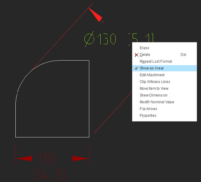
I want Dimensions type as marked in green color, but when I'm retriving dimensions from model I'm getting like as marked in red color. I'm tried with dimension code placing in driven dimension also.
Thanks and Regards,
Naveen Kumar Gongu
- Mark as New
- Bookmark
- Subscribe
- Mute
- Subscribe to RSS Feed
- Permalink
- Notify Moderator
I do not having that problem, I have tried with one sample model, attaching for your reference. the dimensions are retrieved from model dimensions.
It would be better if you can upload your file,
- Mark as New
- Bookmark
- Subscribe
- Mute
- Subscribe to RSS Feed
- Permalink
- Notify Moderator
Are you done this by using extrude feature?
I'm getting the problem when I used revolve feature in the model.
- Mark as New
- Bookmark
- Subscribe
- Mute
- Subscribe to RSS Feed
- Permalink
- Notify Moderator
understand your problem, do not have solution, sorry.
- Mark as New
- Bookmark
- Subscribe
- Mute
- Subscribe to RSS Feed
- Permalink
- Notify Moderator
Thank you 🙂
- Mark as New
- Bookmark
- Subscribe
- Mute
- Subscribe to RSS Feed
- Permalink
- Notify Moderator
Did you try unchecking the "show as linear" in your drawing dimension

- Mark as New
- Bookmark
- Subscribe
- Mute
- Subscribe to RSS Feed
- Permalink
- Notify Moderator
Yes Praveen Kumar.
- Mark as New
- Bookmark
- Subscribe
- Mute
- Subscribe to RSS Feed
- Permalink
- Notify Moderator
I do tried it using revolve and getting the same as you..
- Mark as New
- Bookmark
- Subscribe
- Mute
- Subscribe to RSS Feed
- Permalink
- Notify Moderator
We have had the same problem. When creating a radius with the revolve command the software only allows the dimension to be shown as a "linear". The only solution that we have found is what someone else already mentioned. The feature must be made as an extrude. I searched the PTC call database and could not find where anyone has ever reported this as a problem to PTC.
- Mark as New
- Bookmark
- Subscribe
- Mute
- Subscribe to RSS Feed
- Permalink
- Notify Moderator
It's an interesting problem. The dimensions are shown as reported by Sketcher to the drawing. In Sketcher the section doesn't have a radius dimension, only a linear one that might be, but isn't necessarily, to the axis of revolution. When placing them on the drawing, linear dimensions are moved perpendicular to the sketch plane.
For example, one might be creating a tube with a wall thickness. In this case, one dimension will be to the axis of revolution, but the other isn't, though both are in a radial direction.
So one dimension would have to be converted to a radius/diameter and the other one not converted. However, the wall thickness dimension could be replaced/redefined in Sketcher to represent a radius/diameter. Now it moves from not being converted into a radius/diameter to being converted into a diameter.
It seems to me that PTC could add a special case conversion for any dimensions that reference an in-Sketcher axis of revolution without a large amount of difficulty, and those that happen to coincide with an external axis of revolution with a little more difficulty.
The bigger effort is changing the drawing software to handle axis-normal views by making the orientation of the dimension angle independent of the original sketching plane.
- Mark as New
- Bookmark
- Subscribe
- Mute
- Subscribe to RSS Feed
- Permalink
- Notify Moderator
Thank you all of you for your time spent on my problem. ![]()
Regards,
Naveen Kumar Gongu.


