
Turn on suggestions
Auto-suggest helps you quickly narrow down your search results by suggesting possible matches as you type.
Showing results for
Please log in to access translation
Turn on suggestions
Auto-suggest helps you quickly narrow down your search results by suggesting possible matches as you type.
Showing results for
- Community
- Creo+ and Creo Parametric
- 3D Part & Assembly Design
- Re: How to create a triangular surface patch witho...
Translate the entire conversation x
Please log in to access translation
Options
- Subscribe to RSS Feed
- Mark Topic as New
- Mark Topic as Read
- Float this Topic for Current User
- Bookmark
- Subscribe
- Mute
- Printer Friendly Page
How to create a triangular surface patch without wrinkle
Sep 21, 2015
11:32 PM
- Mark as New
- Bookmark
- Subscribe
- Mute
- Subscribe to RSS Feed
- Permalink
- Notify Moderator
Please log in to access translation
Sep 21, 2015
11:32 PM
How to create a triangular surface patch without wrinkle
Hi, I am facing an issue here when I try to add a triangular patch to my quilt. If I create the patch using boundary blend (2+1 curves), the resultant surface will have a wrinkled tip which will then prevent me from the subsequent thickness offset. Any good way to create a nice wrinkle free surface for this ? I attached my part file here for your reference. Thanks.
20 REPLIES 20
Sep 22, 2015
01:08 AM
- Mark as New
- Bookmark
- Subscribe
- Mute
- Subscribe to RSS Feed
- Permalink
- Notify Moderator
Please log in to access translation
Sep 22, 2015
01:08 AM
When I create this patch, I don't necessarily get "wrinkles" but I think I see what you mean.
Assuming you cannot alter the tangency settings of the surface, the best option is not to use a boundary blend at all. I already tried messing with the tangency and it doesn't help. The patch just fails. So instead, branch out and try something new... a Style surface.
A style surface offers several options not available with a typical boundary blend. You can generate the surface and then partition and edit it to tweak it until it's in the precise shape you need. I was able to create a Style surface without a wrinkle and then offset it nicely. Surfacing using the style menu is far beyond what I can explain in a post but I'll give you the general steps.
Select Style from the Model-->Surfaces tab. Select Surface from the style menu. Choose all 3 edges of your triangle and select the check mark to complete the feature. This will create a basic triangular patch. You can subdivide the patch by selecting Surface Edit and then adding to the Max Rows and Max Columns.
This is the most basic possible set of options for a style surface. Hopefully, this gives you enough to start with. You can investigate other style options further to help you develop high quality surfaces patches and use them as the basis for downstream geometry,
Good luck!
-Brian
Sep 22, 2015
01:47 AM
- Mark as New
- Bookmark
- Subscribe
- Mute
- Subscribe to RSS Feed
- Permalink
- Notify Moderator
Please log in to access translation
Sep 22, 2015
01:47 AM
Thanks, Brian.
In this case (using style), how do i control the tangency of the surface along its 2 curves lying on RIGHT and TOP planes ? I want the surface to be NORMAL to its curve planes. Thanks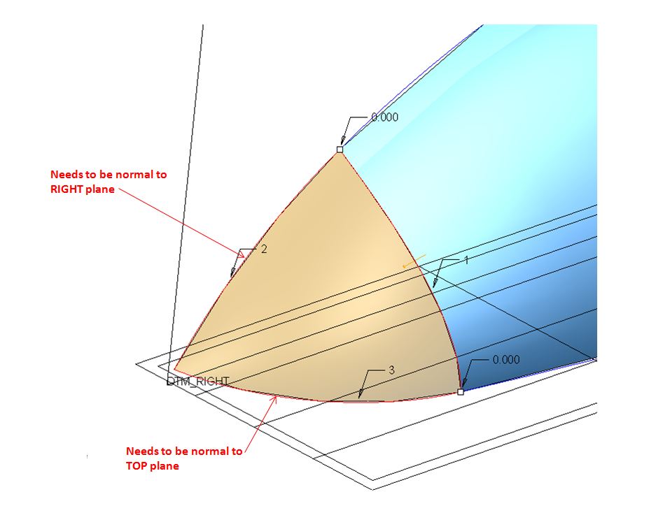
Sep 22, 2015
04:24 PM
- Mark as New
- Bookmark
- Subscribe
- Mute
- Subscribe to RSS Feed
- Permalink
- Notify Moderator
Please log in to access translation
Sep 22, 2015
04:24 PM
You cannot with the current sketches. To make the edge of a surface normal to a plane all the lines intersecting the plane need to be normal. Your sketches are not normal to either plane.
There is always more to learn in Creo.
Sep 22, 2015
01:39 AM
- Mark as New
- Bookmark
- Subscribe
- Mute
- Subscribe to RSS Feed
- Permalink
- Notify Moderator
Please log in to access translation
Sep 22, 2015
01:39 AM
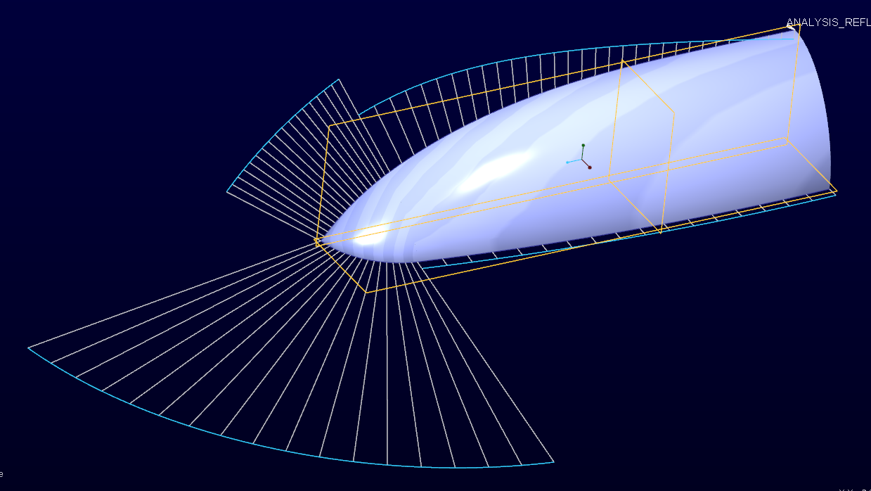
In case you have not purchased the style (ISDX) extension, you can still do it with the basic package with boundary blend as follow:
trimming your first boundary blend (the 3 sided one)
Create a second boundary blend (4 sided) :
You can see the procedure with the file enclosed
Sep 22, 2015
01:53 AM
- Mark as New
- Bookmark
- Subscribe
- Mute
- Subscribe to RSS Feed
- Permalink
- Notify Moderator
Please log in to access translation
Sep 22, 2015
01:53 AM
This resultant surface looks great, except that it looks a bit "patchy". Any way to get rid of those boundary lines of 2nd blended surface ? Thanks
Sep 22, 2015
02:00 AM
- Mark as New
- Bookmark
- Subscribe
- Mute
- Subscribe to RSS Feed
- Permalink
- Notify Moderator
Please log in to access translation
Sep 22, 2015
02:00 AM
You mean in the display ? If yes go in "shading mode" instead of "shading with edges".
Unless your part is going to be a highly glossy surface (for ex a car body) I wouldn't worry about the transition being visible.
In most of the applications (matte / non glossy surface), tangent continuous surfaces are enough (you rarely need to go to curvature continuity).
Sep 22, 2015
10:13 PM
- Mark as New
- Bookmark
- Subscribe
- Mute
- Subscribe to RSS Feed
- Permalink
- Notify Moderator
Please log in to access translation
Sep 22, 2015
10:13 PM
You will not get a smooth surface is the related curves are not joined with curvature continuous edges.
With boundary blends, you can filter vertex to get the point at the end.
I might suggest making the entire surface with new geometry.
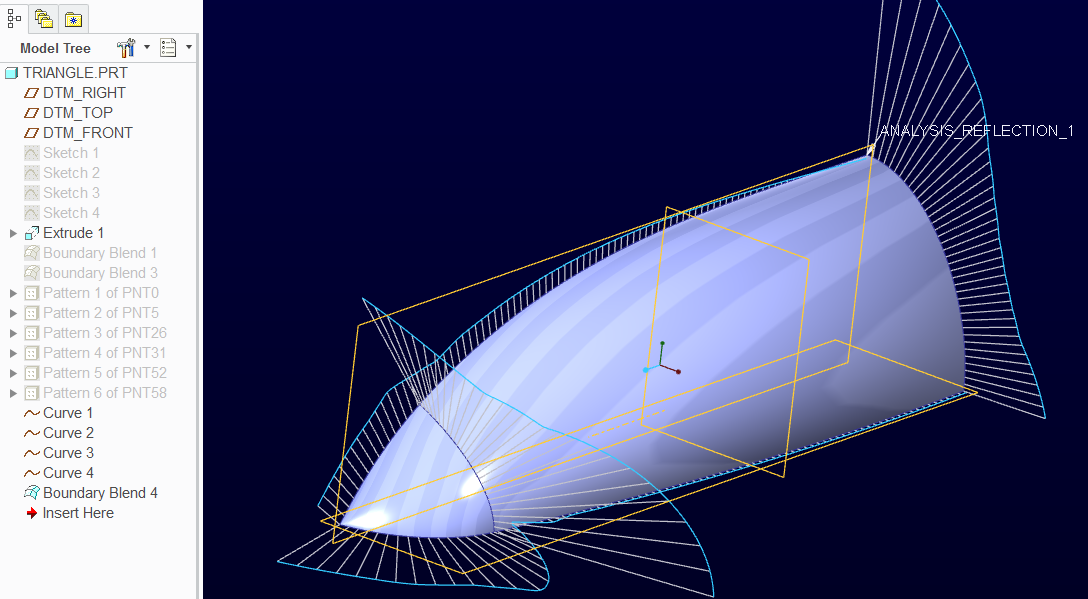
Creo 2.0 attached
Sep 22, 2015
11:15 PM
- Mark as New
- Bookmark
- Subscribe
- Mute
- Subscribe to RSS Feed
- Permalink
- Notify Moderator
Please log in to access translation
Sep 22, 2015
11:15 PM
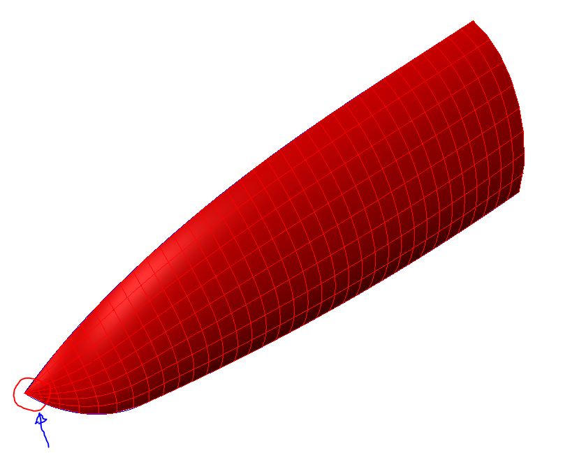
Thanks and the surface is smooth ! Questions:
1. why did you use point as part of its boundary ? Any difference without it?
2. The final surface still has the pointy tip. I have problem to offset it more than 0.14. Any workaround to allow 0.2 offset?
Sep 23, 2015
01:50 AM
- Mark as New
- Bookmark
- Subscribe
- Mute
- Subscribe to RSS Feed
- Permalink
- Notify Moderator
Please log in to access translation
Sep 23, 2015
01:50 AM
There are still limitations due to the original geometry. If you look carefully, there is a bit of a "pooch" where the triangle is filled in.
I have worked with geometry in the past where the edges just do not wish to cooperate. Geometry such as this is easier to create in "oversized" sheets.
Meaning, make the full shape and then trim it to the quarter that you have.
Without the advanced surface extension, you will soon be pulling your hair out to get really nice continuous curvature surfaces out of Creo.
We have to sort of sneak in from the back to get there. Very frustrating!
Even the selection of features and the order of selecting them can change these surfaces in minute ways. I have created support cases to explain this and with great competence and excellent descriptions from the tech only left my mind drained in making these things work.
If this is really critical, keep at it and know that you are fighting an uphill battle. Otherwise, let good enough be just that. The better your defining geometry, the better the results. This kind of effort doesn't recognize arcs and lines but it does recognize turbulence with a vengeance.
To create good results for an offset, generating 2 surfaces from offset curve geometry instead of the surface 
And to show I do understand; most people ask us designers to "just fix it" or simply "make a small tweak", when in fact they have no clue what they are really asking for. The best we can do is to request the original geometry where larger shaped surfaces are still available to maintain their original "fluidity".
Obviously I am not an ID person or all these quotes would have fancy names and descriptions. Point is, much of this type of geometry stems from seed surfaces and intersects. Once lost, your meddling can always be detected by experts. You cannot fool the innate senses.
Sep 23, 2015
02:15 AM
- Mark as New
- Bookmark
- Subscribe
- Mute
- Subscribe to RSS Feed
- Permalink
- Notify Moderator
Please log in to access translation
Sep 23, 2015
02:15 AM
If this is your own, use a freestyle body. If you get good at manipulating a freestyle surface, you can have near perfect "shapes".
This one will offset (using thicken) with perfect scaling.
I don't like the lack of control of freestyle surfaces because it is so hard to copy an existing shape. But it the shape is your own... it can do wonders.
You can also Warp the body if some final tweaks are desired.
Sep 23, 2015
03:21 AM
- Mark as New
- Bookmark
- Subscribe
- Mute
- Subscribe to RSS Feed
- Permalink
- Notify Moderator
Please log in to access translation
Sep 23, 2015
03:21 AM
Thanks, i think this is another feasible solution to my problem. Yeah, I think the limited controls we have on freestyle feature might be an issue to engineering in real life.
Sep 23, 2015
10:01 AM
- Mark as New
- Bookmark
- Subscribe
- Mute
- Subscribe to RSS Feed
- Permalink
- Notify Moderator
Please log in to access translation
Sep 23, 2015
10:01 AM
The style tool is designed to do things like this. It should be much simpler with greater freedom to make true curvature continuous surfaces.
Sep 24, 2015
10:35 AM
- Mark as New
- Bookmark
- Subscribe
- Mute
- Subscribe to RSS Feed
- Permalink
- Notify Moderator
Please log in to access translation
Sep 24, 2015
10:35 AM
Nice work Antonius!
Oct 01, 2015
03:38 PM
- Mark as New
- Bookmark
- Subscribe
- Mute
- Subscribe to RSS Feed
- Permalink
- Notify Moderator
Please log in to access translation
Oct 01, 2015
03:38 PM
Now you guys are just showing off.
Sep 23, 2015
08:26 AM
- Mark as New
- Bookmark
- Subscribe
- Mute
- Subscribe to RSS Feed
- Permalink
- Notify Moderator
Please log in to access translation
Sep 23, 2015
08:26 AM
I think there's a deeper issue than what we discussed: if the surface needs to be normal to one of the planes, then the edge you are using to construct the "triangle patch tip" must be normal to said plane too. Sketch 3 curve is not normal to TOP plane, and the same goes for the other sketch.
With the current sketches you chose sketch 3 and sketch 4 as first direction boundary blends, and that's the issue. If you want the surface to flow better (forget normal as we already saw it's not possible with current sketches) just use sketch 4 and the boundary edge for first direction, with tangent, then sketch 3 as second direction, this should be much smoother
Sep 23, 2015
10:08 AM
- Mark as New
- Bookmark
- Subscribe
- Mute
- Subscribe to RSS Feed
- Permalink
- Notify Moderator
Please log in to access translation
Sep 23, 2015
10:08 AM
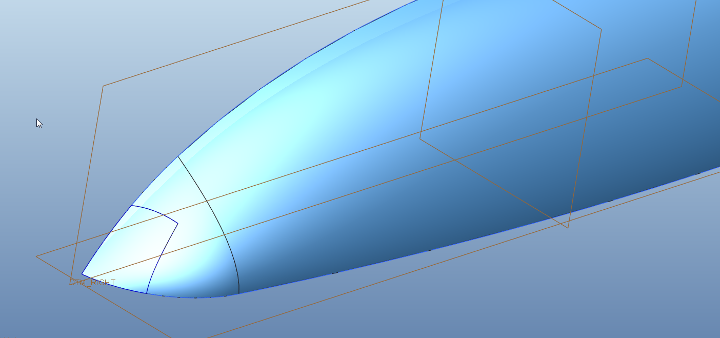
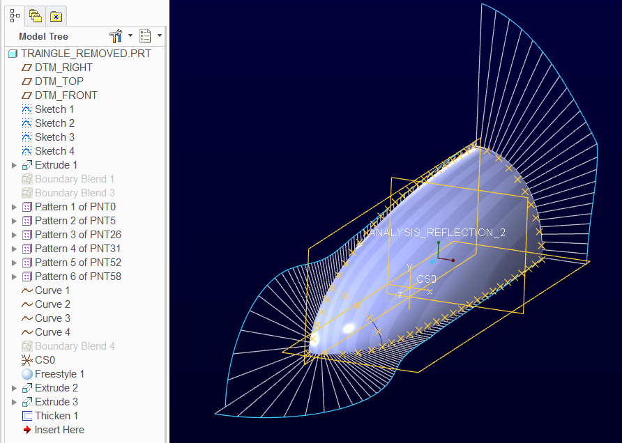
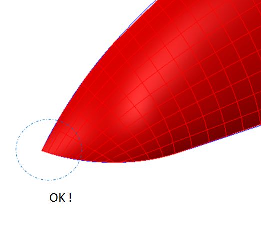
I think I have got another workaround here, quite similar to ccanales's suggestion. See below and attached proe file. With this I am able to get rid of the bad geometry at its tip thus allow me to offset it better. What do you guys think ?
Oct 01, 2015
11:36 PM
- Mark as New
- Bookmark
- Subscribe
- Mute
- Subscribe to RSS Feed
- Permalink
- Notify Moderator
Please log in to access translation
Oct 01, 2015
11:36 PM
Perhaps you have a purpose or reason for it, but I think you started off badly by making the two main boundary curves from two sketched curves tangent to each other. Also, the technique of utilizing the extruded surface to get 4 boundaries is fairly clever, it could, depending on the geometry along that side, result in a less than perfect edge, if you zoom up on the edge of the surface it isn't aligned with the curve that is probably intended to be the edge of the surface. Of course, if this surface is going to be the base surface and other surfaces will align to it, you might be okay with that resulting edge being where it is, rather than where the curve is.
Oct 03, 2015
02:08 AM
- Mark as New
- Bookmark
- Subscribe
- Mute
- Subscribe to RSS Feed
- Permalink
- Notify Moderator
Please log in to access translation
Oct 03, 2015
02:08 AM
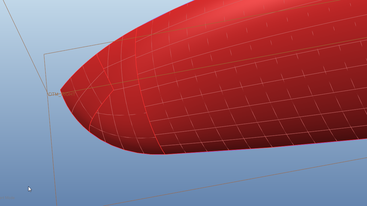
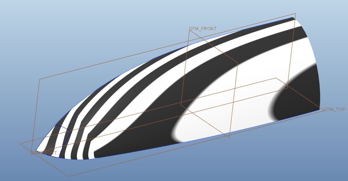
Thanks for pointing out the surface edge and original curve matching issue. One thing I have done to improve the matching is to have standalone section for my extruded surface. I can then tweak the section till the resultant surface edge matches with the original curve pretty well. See below:
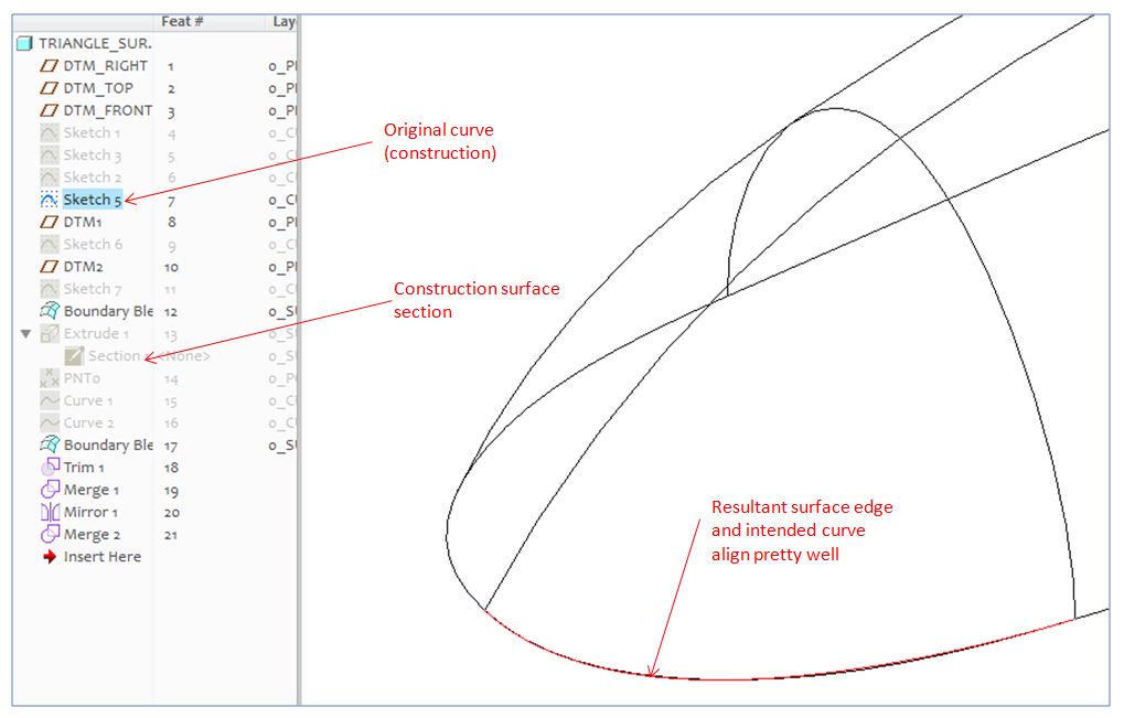
It's pretty manual work, and if there is more engineering way to align then would be good.
Oct 03, 2015
01:08 PM
- Mark as New
- Bookmark
- Subscribe
- Mute
- Subscribe to RSS Feed
- Permalink
- Notify Moderator
Please log in to access translation
Oct 03, 2015
01:08 PM
The better approach is to overbuild a little, along the lines of what you did, but within the intended surface, not outside of it. You can create the three sided surface using the vertex at that pointed corner, trim it out so you have four sides for the final surface, or bring that first surface up a little closer to the sharp corner, trim it out so you have four boundaries for the final surface.
Oct 04, 2015
09:31 PM
- Mark as New
- Bookmark
- Subscribe
- Mute
- Subscribe to RSS Feed
- Permalink
- Notify Moderator
Please log in to access translation
Oct 04, 2015
09:31 PM
Cool, I would like to try out what you suggested. Could you please attached your proe file to ensure I have correct understanding ? Appreciate it. Thanks


