Community Tip - Did you get an answer that solved your problem? Please mark it as an Accepted Solution so others with the same problem can find the answer easily. X
- Community
- Creo+ and Creo Parametric
- 3D Part & Assembly Design
- Re: How to create tapered corner in model
- Subscribe to RSS Feed
- Mark Topic as New
- Mark Topic as Read
- Float this Topic for Current User
- Bookmark
- Subscribe
- Mute
- Printer Friendly Page
How to create tapered corner in model
- Mark as New
- Bookmark
- Subscribe
- Mute
- Subscribe to RSS Feed
- Permalink
- Notify Moderator
How to create tapered corner in model
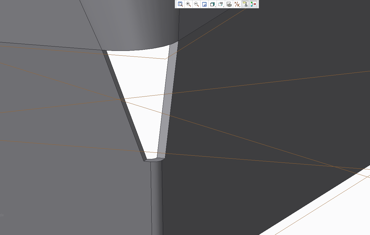
Can anybody help me out and tell me how to create the conical corner in this model.
We usually model this as plates but I want to do FEM analysis using solids.
I have no idea how to fill the gap with a single feature. A picture of the model is added.
Thanks in advance! I'm using CREO 2.0.

This thread is inactive and closed by the PTC Community Management Team. If you would like to provide a reply and re-open this thread, please notify the moderator and reference the thread. You may also use "Start a topic" button to ask a new question. Please be sure to include what version of the PTC product you are using so another community member knowledgeable about your version may be able to assist.
- Labels:
-
General
- Mark as New
- Bookmark
- Subscribe
- Mute
- Subscribe to RSS Feed
- Permalink
- Notify Moderator
Hi Steven.
Thanks for your reply.
I already tried the Boudary blend with Thicken. First off, it made some really confusing looking solids. Now the blend does't work anymore.
The problem is that the point transforms from an ellipse to a circular surface. Apparently, this seems to be a problem with Inventor to make a closed solid 3D model as well. I am going to approach the shape by going from circular to circular. The original shape was made up in an assembly for production where the plates have small gaps. In production they weld the arrangement, so it doesn’t matter. But for my analysis it just won’t work ;).
So I tried to be lazy/practical and use part of their model and make quick adjustments for my analysis. I was wondering if I missed some of Creo’s capabilities to be able to fix this problem as it is.
So I’m curious to know if it’s doable.
I uploaded the model so you can have a look.
Thanks again!
- Mark as New
- Bookmark
- Subscribe
- Mute
- Subscribe to RSS Feed
- Permalink
- Notify Moderator
Hi Steven. How do I upload the model?. I can only find insert i,age/video
- Mark as New
- Bookmark
- Subscribe
- Mute
- Subscribe to RSS Feed
- Permalink
- Notify Moderator
This link tells you how to upload a model. How to Attach a File to a Discussion Reply
- Mark as New
- Bookmark
- Subscribe
- Mute
- Subscribe to RSS Feed
- Permalink
- Notify Moderator
Thanks!
- Mark as New
- Bookmark
- Subscribe
- Mute
- Subscribe to RSS Feed
- Permalink
- Notify Moderator
I got it. But it is still "Currenly being moderated".
So waiting for apporval ![]()
- Mark as New
- Bookmark
- Subscribe
- Mute
- Subscribe to RSS Feed
- Permalink
- Notify Moderator
- Mark as New
- Bookmark
- Subscribe
- Mute
- Subscribe to RSS Feed
- Permalink
- Notify Moderator
Hi Steven,
Thanks for the info. I had already tried making the boundary blends on both sides of the surfaces. Because of the thicken surface from the left vertical "wall" the surface blend maintains a tiny gap in the upper left corner. I can't quite seem to get closed surfaces to create a solid from solidify.
You mentioned using the sweep. My knowlegde of this function limits itself to sweep where the trajectory is perpendicular to the sketch. Therfore I'm not quite sure how to make use of the fucntion for this purpose.
- Mark as New
- Bookmark
- Subscribe
- Mute
- Subscribe to RSS Feed
- Permalink
- Notify Moderator
Just by looking at your picture (and not the model), the top part of the opening appears to be lined up to the tangency of the rads and the bottom is not. Is that on purpose? It seems like it would blend a lot easier if top and bottom were similar.
- Mark as New
- Bookmark
- Subscribe
- Mute
- Subscribe to RSS Feed
- Permalink
- Notify Moderator
Hi,
your model contains imported geometry. You are adding some other geometry to it. Is it necessary to work this way ? I think you can build additional geometry in separate part and assemble it to imported part.
MH
Martin Hanák


