
Turn on suggestions
Auto-suggest helps you quickly narrow down your search results by suggesting possible matches as you type.
Showing results for
Please log in to access translation
Turn on suggestions
Auto-suggest helps you quickly narrow down your search results by suggesting possible matches as you type.
Showing results for
Community Tip - Your Friends List is a way to easily have access to the community members that you interact with the most! X
- Community
- Creo+ and Creo Parametric
- 3D Part & Assembly Design
- Interferance Report Error
Translate the entire conversation x
Please log in to access translation
Options
- Subscribe to RSS Feed
- Mark Topic as New
- Mark Topic as Read
- Float this Topic for Current User
- Bookmark
- Subscribe
- Mute
- Printer Friendly Page
Interferance Report Error
Aug 05, 2015
02:32 PM
- Mark as New
- Bookmark
- Subscribe
- Mute
- Subscribe to RSS Feed
- Permalink
- Notify Moderator
Please log in to access translation
Aug 05, 2015
02:32 PM
Interferance Report Error
Creo 2 Parametric, M160
When I do an global interference on my assy, two parts report a very high interference, about 7.5 cubic inches. There is no clear interferance between the parts. This value is consistent between a global interference or pairs clearance checks ,whether at the top level or at the sub assy level. I created a cut out of one part into the other, which should eliminate all interferences and it still reports the same value. In fact, it turns out the volume reported is exactly equal to the volume of the two parts together. For some reason Creo thinks they fully overlap when they clearly do not.
Has anyone seen this before and have a work around? My concern is trusting the analysis in other areas, or missing and actual interference between these two parts because I assume this is just a glitch.
Solved! Go to Solution.
Labels:
- Labels:
-
General
ACCEPTED SOLUTION
Accepted Solutions
Mar 21, 2016
11:30 AM
- Mark as New
- Bookmark
- Subscribe
- Mute
- Subscribe to RSS Feed
- Permalink
- Notify Moderator
Please log in to access translation
Mar 21, 2016
11:30 AM
Doug Schaefer, I just retested this issue in CP3 M080 and it appears to now be resolved. Tech support has never updated my case, so I just emailed them to find out what build it was corrected in. I'll let you know...
21 REPLIES 21
Aug 05, 2015
03:31 PM
- Mark as New
- Bookmark
- Subscribe
- Mute
- Subscribe to RSS Feed
- Permalink
- Notify Moderator
Please log in to access translation
Aug 05, 2015
03:31 PM
This may sound silly, but are you in an exploded view or a drawing snapshot? IE maybe the parts really are overlapped?
Have you tried putting them in a brand new assembly with a distance of 100 units apart?
Aug 06, 2015
10:47 AM
- Mark as New
- Bookmark
- Subscribe
- Mute
- Subscribe to RSS Feed
- Permalink
- Notify Moderator
Please log in to access translation
Aug 06, 2015
10:47 AM
No, in fact I've since seen it in another sub-assy in the same database. This time it was with screws where I'd expect a small interference, but it showed the entirety of both parts as overlapping.
Unfortunately, we are not current on maintenance so I cannot send it to tech support to evaluate.
Aug 06, 2015
11:10 AM
- Mark as New
- Bookmark
- Subscribe
- Mute
- Subscribe to RSS Feed
- Permalink
- Notify Moderator
Please log in to access translation
Aug 06, 2015
11:10 AM
Are you able to share the models? I can test it in the latest version of Creo, and I do have maintenance if necessary. 
Aug 06, 2015
11:15 AM
- Mark as New
- Bookmark
- Subscribe
- Mute
- Subscribe to RSS Feed
- Permalink
- Notify Moderator
Please log in to access translation
Aug 06, 2015
11:15 AM
They are client models,i'd have to get permission to share them. I do have Creo 3 loaded, I can give them a try there to see if I get the same results.
Aug 06, 2015
11:26 AM
- Mark as New
- Bookmark
- Subscribe
- Mute
- Subscribe to RSS Feed
- Permalink
- Notify Moderator
Please log in to access translation
Aug 06, 2015
11:26 AM
OK, it seems that today, after shutting a restart of both Creo & my laptop, I cannot reproduce the issue in the the initial assy, but it remains in the other. No changes have been made in any of the components involved.
Here's a detail screenshot of the two parts, a screw (McMaster download) and a plastic panel:
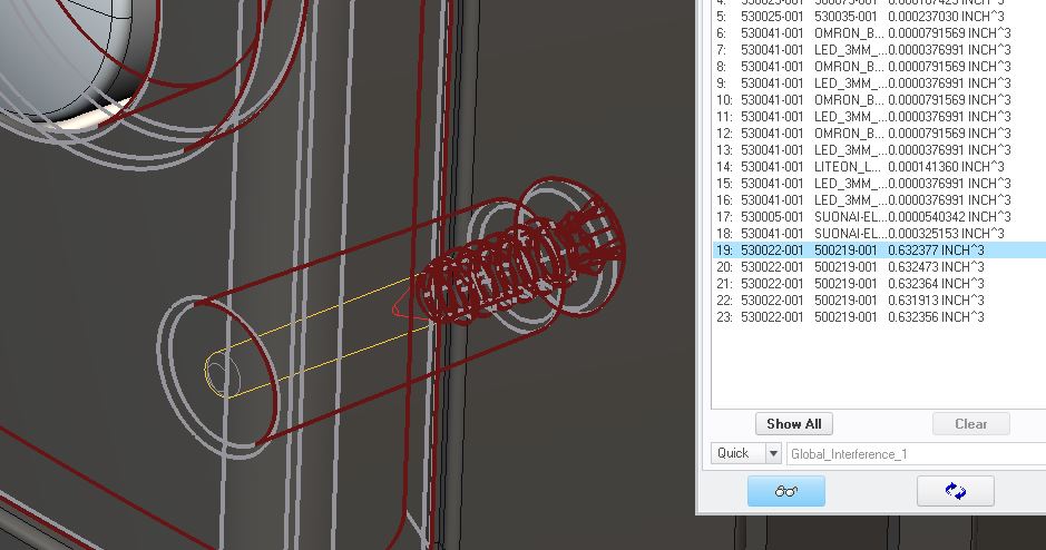
Interestingly, the reported interference between multiple instances of the same screw is not identical, but very close. The volume of the panel is 0.629878, the volume of the screw is 0.001687. Combined volume is 0.631565. In the first occurrence the reported interference was exactly the combined volume of the two parts (both molded parts in that case), in this case it is not.
Aug 06, 2015
11:30 AM
- Mark as New
- Bookmark
- Subscribe
- Mute
- Subscribe to RSS Feed
- Permalink
- Notify Moderator
Please log in to access translation
Aug 06, 2015
11:30 AM
Just out of curiosity, did you download a Creo model from McMaster or a neutral file (STEP or IGES)?
Aug 06, 2015
11:34 AM
- Mark as New
- Bookmark
- Subscribe
- Mute
- Subscribe to RSS Feed
- Permalink
- Notify Moderator
Please log in to access translation
Aug 06, 2015
11:34 AM
STEP file. it is solid with no geom checks. It was created in WF4.
Keep in mind, the first occurrence was with two native Creo files.
Aug 06, 2015
11:32 AM
- Mark as New
- Bookmark
- Subscribe
- Mute
- Subscribe to RSS Feed
- Permalink
- Notify Moderator
Please log in to access translation
Aug 06, 2015
11:32 AM
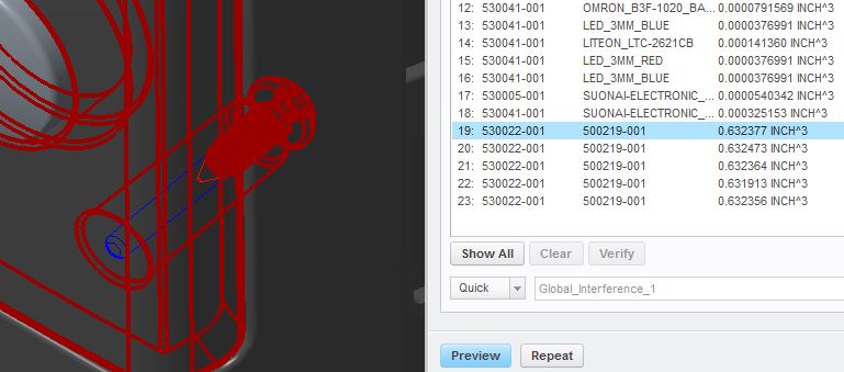
Creo 3, M040 reports the same results:
Aug 06, 2015
11:42 AM
- Mark as New
- Bookmark
- Subscribe
- Mute
- Subscribe to RSS Feed
- Permalink
- Notify Moderator
Please log in to access translation
Aug 06, 2015
11:42 AM
How can the interference be larger than the combined volume of the parts??? Even with no holes in the plastic part, the total interference should not exceed the volume of one screw. Does the amount of interference change if you suppress the screw holes in the panel?
Aug 06, 2015
11:46 AM
- Mark as New
- Bookmark
- Subscribe
- Mute
- Subscribe to RSS Feed
- Permalink
- Notify Moderator
Please log in to access translation
Aug 06, 2015
11:46 AM
I'll look into it later, I've got to get some files out. 
Aug 06, 2015
02:56 PM
- Mark as New
- Bookmark
- Subscribe
- Mute
- Subscribe to RSS Feed
- Permalink
- Notify Moderator
Please log in to access translation
Aug 06, 2015
02:56 PM
Hate it when work gets in the way of a good mystery. 
Aug 06, 2015
04:10 PM
- Mark as New
- Bookmark
- Subscribe
- Mute
- Subscribe to RSS Feed
- Permalink
- Notify Moderator
Please log in to access translation
Aug 06, 2015
04:10 PM
Yep.
I did ask a colleague and the client to look at it and they all got the same result.
Tomorrow is a bit lighter, I can play with it a bit.
Aug 10, 2015
10:03 AM
- Mark as New
- Bookmark
- Subscribe
- Mute
- Subscribe to RSS Feed
- Permalink
- Notify Moderator
Please log in to access translation
Aug 10, 2015
10:03 AM
The ID & OD of the boss were made with the same feature, but I made the ID construction geometry in the sketch and suppressed the related draft & round. I then got a result that makes sense:
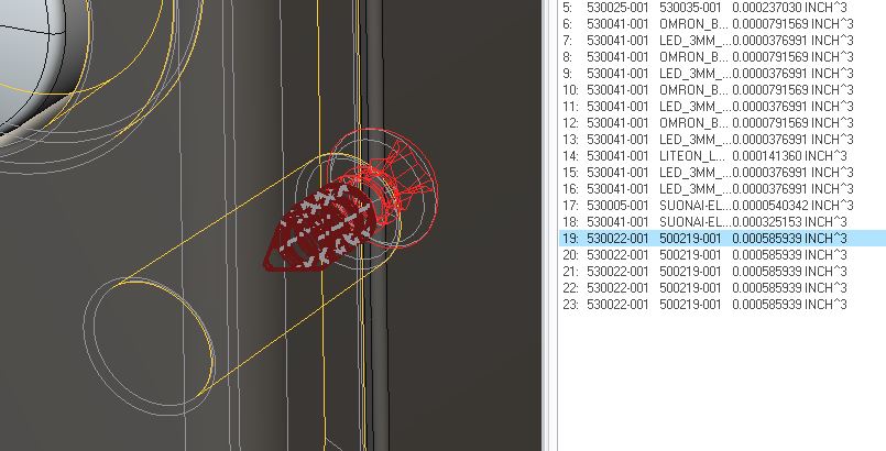
Restoring the hole, draft and round returned the same, odd results. I also tried suppressing the draft and round, leaving the ID. That also produced reasonable results:
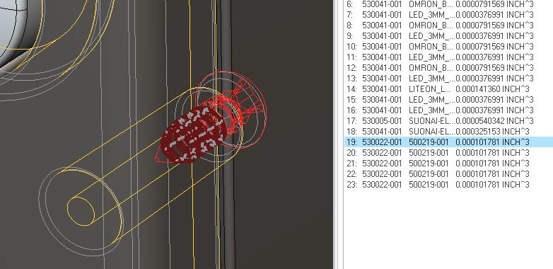
With just the draft and not the round, I got odd results again.
The draft makes the Id of the hole interfere with the minor dia. of the screw near the tip, but is clear of the minor dia at the head. That shouldn't give the results I'm seeing, but I wonder if that's contributing to it?
Aug 10, 2015
11:09 AM
- Mark as New
- Bookmark
- Subscribe
- Mute
- Subscribe to RSS Feed
- Permalink
- Notify Moderator
Please log in to access translation
Aug 10, 2015
11:09 AM
I am unable to reproduce the issue in Creo 3. I'm wondering if the problem is specific to that model. If you create a new test model with a similar boss and the assemble the same screw to it, do you still see the same problem?
Aug 10, 2015
11:25 AM
- Mark as New
- Bookmark
- Subscribe
- Mute
- Subscribe to RSS Feed
- Permalink
- Notify Moderator
Please log in to access translation
Aug 10, 2015
11:25 AM
Yes, with a simple panel with a boss of identical dimensions, a simple PCB and the same screw I get similar results. I've attached that assy in a zip file (Creo 2, M160).
If you change the ID draft (Draft 1) to zero, the odd results go away.
Aug 10, 2015
11:41 AM
- Mark as New
- Bookmark
- Subscribe
- Mute
- Subscribe to RSS Feed
- Permalink
- Notify Moderator
Please log in to access translation
Aug 10, 2015
11:41 AM
Yep, I'm seeing the same issue in Creo 3. Let me open a case with tech support.
Aug 10, 2015
11:49 AM
- Mark as New
- Bookmark
- Subscribe
- Mute
- Subscribe to RSS Feed
- Permalink
- Notify Moderator
Please log in to access translation
Aug 10, 2015
11:49 AM
Changing the draft angle to 2 degrees (more interference) also generates accurate interference values.
Aug 10, 2015
11:57 AM
- Mark as New
- Bookmark
- Subscribe
- Mute
- Subscribe to RSS Feed
- Permalink
- Notify Moderator
Please log in to access translation
Aug 10, 2015
11:57 AM
I only tried 0.5 degree and 1.0 degree, but found the same results. Only zero draft produced accurate results.
Thanks for opening a case, hopefully there's a simple fix. Thankfully, at least in the situations I've seen, the error is large enough to be very obvious.
Mar 21, 2016
11:30 AM
- Mark as New
- Bookmark
- Subscribe
- Mute
- Subscribe to RSS Feed
- Permalink
- Notify Moderator
Please log in to access translation
Mar 21, 2016
11:30 AM
Doug Schaefer, I just retested this issue in CP3 M080 and it appears to now be resolved. Tech support has never updated my case, so I just emailed them to find out what build it was corrected in. I'll let you know...
Mar 22, 2016
09:23 AM
- Mark as New
- Bookmark
- Subscribe
- Mute
- Subscribe to RSS Feed
- Permalink
- Notify Moderator
Please log in to access translation
Mar 22, 2016
09:23 AM
Tom,
I had forgotten about this, thanks for following up. I tried the original assy and CP3 M070 and it seems fixed there as well. I don't have a build of CP2 newer than M160 installed to try it there.
Apr 12, 2018
10:08 AM
- Mark as New
- Bookmark
- Subscribe
- Mute
- Subscribe to RSS Feed
- Permalink
- Notify Moderator
Please log in to access translation
Apr 12, 2018
10:08 AM
I finally received a response from PTC... after 2 years. This has been corrected in Creo Parametric 3.0 M140 and 4.0 F000.
https://www.ptc.com/en/support/article?n=CS215787

https://support.ptc.com/appserver/cs/view/spr.jsp?n=4700475


