Community Tip - Your Friends List is a way to easily have access to the community members that you interact with the most! X
- Community
- Creo+ and Creo Parametric
- 3D Part & Assembly Design
- Is there an option of applying a remote load/force...
- Subscribe to RSS Feed
- Mark Topic as New
- Mark Topic as Read
- Float this Topic for Current User
- Bookmark
- Subscribe
- Mute
- Printer Friendly Page
Is there an option of applying a remote load/force on Creo Simulate?
- Mark as New
- Bookmark
- Subscribe
- Mute
- Subscribe to RSS Feed
- Permalink
- Notify Moderator
Is there an option of applying a remote load/force on Creo Simulate?
Hi,
I need to run an analysis for a bicycle crank arm. The model provided is only the crank arm and it doesnt include the pedal platform where the pedal load is being applied by the rider. is there is an option of setting the pedal load as a remote force applied on the hole surface (where the pedal shaft connects)?
Your help will be highly appreciated ![]()
Solved! Go to Solution.
- Labels:
-
Surfacing
Accepted Solutions
- Mark as New
- Bookmark
- Subscribe
- Mute
- Subscribe to RSS Feed
- Permalink
- Notify Moderator
Hello,
If I understand clearly your question, Yes this is possible.
First create à point on your part representing the center of the missing pedal.
Now in mechanica apply a load on the surfaces of the axis of the pedal. Then choose "Advanced" , "total load apply to a point" and select your point.
That should give you this kind of result :
Best regards
Christian
- Mark as New
- Bookmark
- Subscribe
- Mute
- Subscribe to RSS Feed
- Permalink
- Notify Moderator
Hi Christian,
Many thanks for the reply! I have tried doing this method and got the following result..

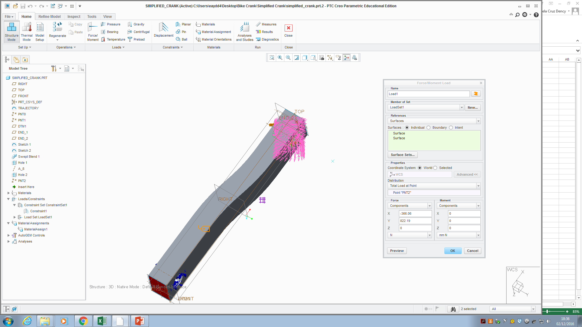
The force is not being applied to the point like in your example and Im getting a weird looking load being applied on the surface instead. I need to set the components of the force as 822N and 360N in the y and x directions respectively to simulate the worst case loading on the crank at a specific angle. Would you know how i should go about this? Thanks
- Mark as New
- Bookmark
- Subscribe
- Mute
- Subscribe to RSS Feed
- Permalink
- Notify Moderator
Possibly you are using a different version that displays the load differently.
Why not create a feature to simulate the crank?
- Mark as New
- Bookmark
- Subscribe
- Mute
- Subscribe to RSS Feed
- Permalink
- Notify Moderator
Hello,
The illustration you give seems ok.
Creo shows you the resulting field of forces you'll have by applying the load at the point.
By selecting "OK" you should then see the load at the point.
What I find curious in your example is the load you applied; is there really a “Y” component? I would have expected a “Z” one instead.
Best regards
Christian
- Mark as New
- Bookmark
- Subscribe
- Mute
- Subscribe to RSS Feed
- Permalink
- Notify Moderator
Christian - Thanks. I'm an Ansys user that is test driving Live Simulation for my company. I do a lot of remote load FEA's. This was very helpful. Thanks again!


